
Double-plate linear motion eddy current retarder
A technology of eddy current damper and linear motion, applied in the direction of spring/shock absorber, spring, magnetic spring, etc., can solve the problems of inconvenient maintenance, harsh working environment of spacecraft dampers, etc., and achieve high reliability and good electromagnetic compatibility characteristics, the effect of a large damping ratio
- Summary
- Abstract
- Description
- Claims
- Application Information
AI Technical Summary
Problems solved by technology
Method used
Image

Examples
Embodiment Construction
[0027] The present invention will be described in detail below with reference to the accompanying drawings and examples.
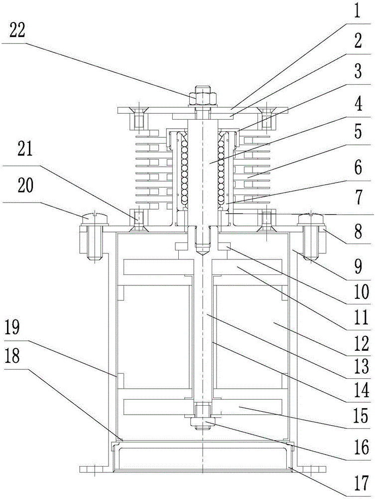
[0028] The invention provides a double-plate linear motion eddy current damper, see attached figure 1 , including: upper flange 1, upper buffer pad 2, upper end cover 3, center shaft 4, spring 5, linear bearing 6, bearing pad 7, installation cylinder 8, outer cylinder 9, lower buffer pad 10, first metal plate 11. Permanent magnet 12, connecting shaft 13, support tube 14, second metal plate 15, compression nut 16, lower end cover 17, magnetic shielding end cover 18, magnetic shielding cylinder 19, outer screw 20, inner screw 21 and central shaft Nut 22;
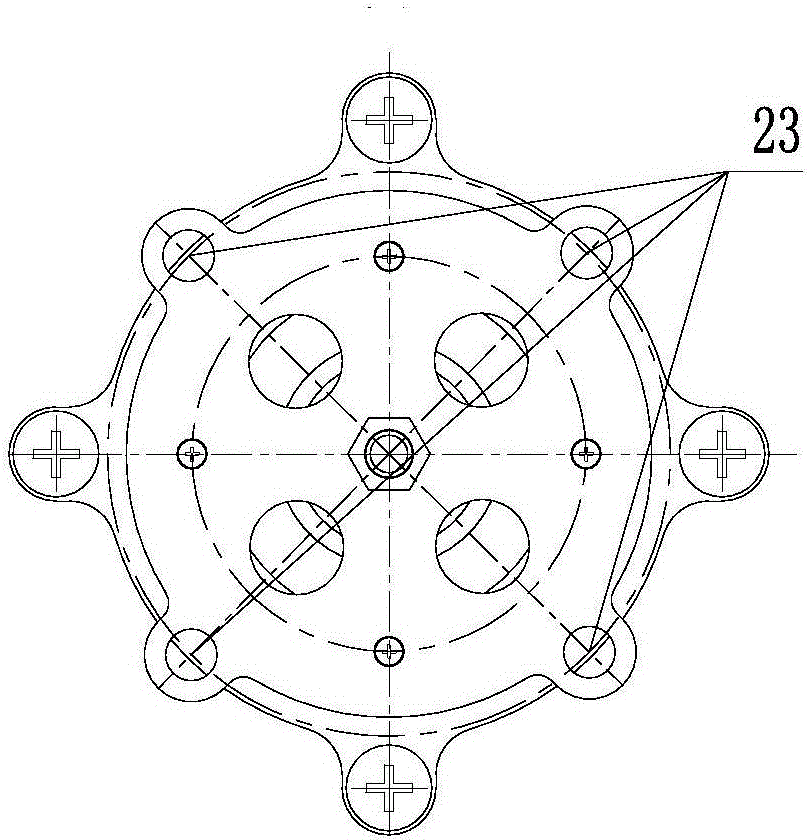
[0029] See attached figure 2 , the upper flange 1 is provided with an installation interface 23 for connecting with an external load device;
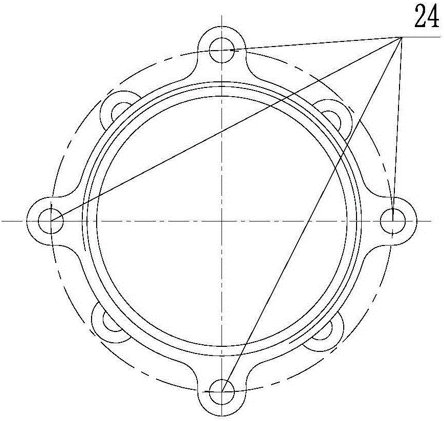
[0030] See attached image 3 , the bottom of the outer cylinder 9 is provided with a connection interface 24 for connecting with the installation base;
[003...
PUM
 Abstract
Description
Claims
Application Information