Rail transit non-contact power supply device with honeycomb-type coils and power supply method thereof

A non-contact power supply and rail transit technology, applied in the direction of circuit devices, electrical components, electromagnetic wave systems, etc., can solve the problems of low magnetic field utilization rate, small effective induction area, low magnetic field strength, etc., achieve high magnetic field utilization rate and reduce electromagnetic waves. Radiation, the effect of increasing the distribution density

Active Publication Date: 2014-05-14
SOUTHWEST JIAOTONG UNIV
View PDF4 Cites 6 Cited by
  • Summary
  • Abstract
  • Description
  • Claims
  • Application Information

AI Technical Summary

Problems solved by technology

There are many problems in this direct contact power supply mode: the direct contact transmission mode of the wire is easily affected by external corrosion, water dust and dirt; the exposed wire is prone to carbon deposits, abrasion, electric sparks, etc. There are dangers; long-distance power transmission Lines take up a lot of space and metal, and will seriously restrict the wiring engineering of wired networks in special geographical operating environments (such as mountains, lakes, etc.)
The existing problems are: the coil distribution is sparse, the generated magnetic field strength is low, and the power supply power is low; and during the whole time period when the locomotive enters the power supply section to pick up power by induction, the entire long rectangular power supply coil is in the energized state, and the coil is picked up at every moment It can only take power from a small area of ​​local induction in the long rectangular power supply coil, the effective induction area is small, the utilization rate of the magnetic field is low, resulting in waste of energy and large electromagnetic radiation

Method used


Image

  • Rail transit non-contact power supply device with honeycomb-type coils and power supply method thereof
  • Rail transit non-contact power supply device with honeycomb-type coils and power supply method thereof
  • Rail transit non-contact power supply device with honeycomb-type coils and power supply method thereof

Examples


Embodiment

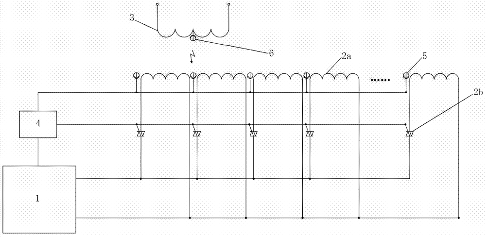
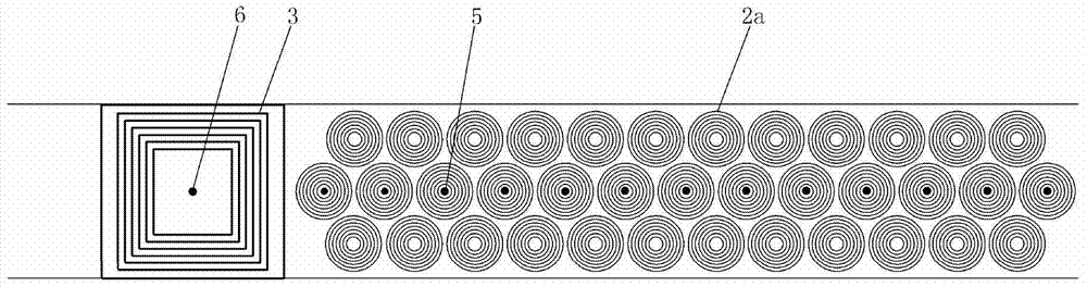
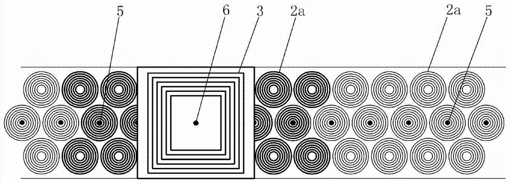
[0021] Figure 1-3 It is shown that a specific embodiment of the present invention is a cellular coil rail transit non-contact power supply device, including a pickup coil 3 at the bottom of a locomotive, a controller 4 and a controller 4 of the power supply station, and AC-DC-AC frequency conversion The AC-DC-AC converter 1 is connected to the power supply coil buried under the ground surface of the track power supply section at the same time. The small power supply coil 2a is composed in parallel, each small power supply coil 2a is connected in series with a switch tube 2b, and the control end of the switch tube 2b is connected to the controller 4; the distance between the small power supply coil 2a on the center line of the track power supply section is set every other A signal receiver 5 for detecting the pickup coil 3 is also connected to the controller 4; a signal generator 6 is provided on the pickup coil 3.

[0022] The specific method of using the cellular coil non-cont...


PUM


Abstract

Disclosed are a rail transit non-contact power supply device with honeycomb-type coils and a power supply method of the rail transit non-contact power supply device. The power supply device comprises a pickup coil and a controller of a power supply station, wherein the pickup coil is arranged at the bottom of a locomotive. The controller is connected with an ADA converter, and the ADA converter is connected with a power supply coil buried below the earth surface of a track power supply section, wherein the power supply coil is formed by connecting a plurality of small power supply coil bodies in parallel, and the small power supply coil bodies are equal in size, are distributed below the earth surface of the whole track power supply section in a honeycomb mode and are in series connection with switching tubes respectively. The control ends of the switching tubes are connected with the controller. Signal receivers for detecting the pickup coil are evenly arranged on the center line of the earth surface of the track power supply section at intervals of the distance of a small power supply coil body and are connected with the controller. A signal generator is arranged on the pickup coil. The non-contact power supply device is high in power supply power and magnetic field utilization ratio, saves energy resources and obviously reduces electromagnetic radiation.

Description

Technical field [0001] The invention relates to a cellular type coil rail transit non-contact power supply device and a power supply method thereof. Background technique [0002] At present, the main power supply mode of rail vehicles is that the pantograph of the locomotive is in contact with the catenary along the track, and electricity is drawn from the catenary. This kind of direct contact power supply has many problems: the transmission method of direct contact with wires is susceptible to external corrosion, water, dust and dirt; worn and exposed wires are prone to carbon deposits, wear, and sparks; long-distance power transmission The line takes up a lot of space and metal, and when it encounters a special geographical operating environment (such as mountains, lakes, etc.), it will seriously restrict the wiring project of the wired network. The use of non-contact power transmission technology can avoid the above-mentioned various similar accidents and simplify the power s...

Claims


Application Information

Patent Timeline
Patent Type & Authority Applications(China)
IPC IPC(8): H02J17/00H02J5/00H02J50/10
Inventor 何正友黄立敏李砚玲林圣麦瑞坤
Owner SOUTHWEST JIAOTONG UNIV
Why Eureka
Try Eureka