Rotary joint for water-cooled roller

A technology of rotary joint and water-cooling roller, applied in the direction of pipe/pipe joint/pipe fitting, adjustable connection, passing element, etc., can solve the problems of aggravating the wear, damage and rapid wear of the sealing ring, so as to prolong the service life and ensure the operation. The effect of precision

Inactive Publication Date: 2016-07-27
武汉钢铁有限公司
View PDF4 Cites 4 Cited by
  • Summary
  • Abstract
  • Description
  • Claims
  • Application Information

AI Technical Summary

Problems solved by technology

[0004] When the cooling water system breaks down, the temperature of the water in the internal circulation circuit of the roller body will continue to rise, even reaching the boiling point, the temperature of the bearing and the bearing seat will also rise rapidly, and the temperature of the lubricating grease will also rise accordingly. Running at high temperature, the service life will drop sharply, and even damage will occur, causing a series of failures
[0005] At present, the service life of domestic rotary joints is short, the main reason is that the manufacturing precision and assembly precision of the components of the rotary joint are average, and the material of the sealing ring is basically the same as that of imported products, but due to the general accuracy, the dynamic ring part and the static ring part of the sealing ring are stressed Unbalanced, fast wear, and local water seepage. The accumulated water may seep into the bearing inside the rotary joint as the joint rotates, causing the bearing lubricating grease to emulsify and deteriorate. After a long time, the lubricating grease fails, the bearing rusts, and the gap increases Large, reducing the motion accuracy of the rotating parts, aggravating the wear of the sealing ring, and quickly appearing the phenomenon of water leakage of the rotary joint

Method used


Image

  • Rotary joint for water-cooled roller

Examples


Embodiment Construction

[0015] In order to better understand the present invention, the present invention will be further described below in conjunction with the accompanying drawings and embodiments.

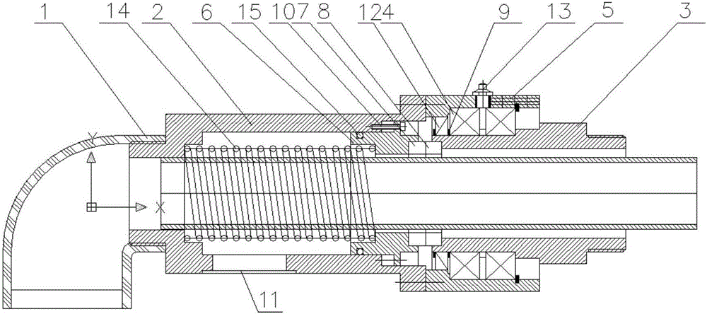
[0016] Such as figure 1 As shown, a rotary joint for water-cooled rollers includes a fixed joint 1, a fixed housing 2, a rotating housing 3, a bearing 4, a bearing seat 5, a spring 14, a sliding seat 6, a fixed sealing ring 7 and a rotating sealing ring 8. One end of the fixed joint and the fixed shell is connected by thread, and the other end of the fixed shell is connected with the bearing seat. The bearing is set between the bearing seat and the rotating shell, and is connected by the retaining ring 9. The sliding seat is adjusted by the adjusting bolt. 10 is fixed on the inner wall of the fixed housing, an O-ring 15 is provided between the sliding seat and the inner wall of the fixed housing, and a lubricating oil nozzle 13 is provided on the bearing seat. The sliding seat can slide a certain dist...


PUM


Abstract

The invention provides a rotary joint for a water-cooled roller. The rotary joint comprises a fixed joint, a fixed casing, a rotary casing, a bearing, a bearing block, a sliding seat, a fixed sealing ring and a rotary sealing ring, wherein the fixed joint is connected with one end of the fixed casing; the other end of the fixed casing is connected with the bearing block; the bearing is arranged between the bearing block and the rotary casing and is positioned and connected through a retainer ring; the sliding seat is fixed on the inner wall of the fixed casing through an adjusting bolt; two ends of a spring are propped against the fixed casing and the sliding seat respectively; the fixed sealing ring is embedded in an end surface of the sliding seat; the rotary sealing ring is embedded in an end surface of the rotary casing; the fixed sealing ring corresponds to the rotary sealing ring; and a water outlet is formed in the bottom of the fixed casing. The operating accuracy of the rotary joint can be guaranteed, and the service life of the rotary joint is prolonged.

Description

technical field [0001] The invention belongs to the technical field of rotary joints, in particular to a rotary joint for water-cooled rolls. Background technique [0002] In iron and steel, papermaking and other industries, water-cooled rolls are widely used, and the working environment where the roll body is located or the temperature of the workpiece in contact with is relatively high. A cooling water circuit is arranged inside the roller body, and is connected with the cooling water at the end of the roller body. Because the roller body rotates in a circle and the cooling water pipe is fixed, it is necessary to install a rotary joint to connect the fixed cooling water pipe and the internal circuit of the rotating roller body. [0003] In steel industry factories, typical water-cooled rolls are water-cooled furnace rolls, water-cooled touch rolls, water-cooled tower top rolls and other rolls of annealing furnaces. The working environment temperature of these rolls ranges...

Claims


Application Information

Patent Timeline
Patent Type & Authority Applications(China)
IPC IPC(8): F16L27/087
CPCF16L27/087
Inventor 陈永朋王小虎李鑫卢振兴
Owner 武汉钢铁有限公司
Why Eureka
Try Eureka