
Experimental method for measuring critical speed influencing factors for steam turbine rotor

A steam turbine rotor and critical speed technology, which is applied in measuring devices, linear/angular velocity measurement, velocity/acceleration/impact measurement, etc., can solve problems such as equipment damage, unit shutdown, rubbing, etc., and achieve far-reaching theoretical significance and engineering practical value , Reduce the effect of abnormal vibration

Inactive Publication Date: 2016-07-27
SHENYANG INST OF ENG
View PDF12 Cites 9 Cited by
  • Summary
  • Abstract
  • Description
  • Claims
  • Application Information

AI Technical Summary

Problems solved by technology

The steam turbine rotor system is composed of the main shaft, impeller, blades and couplings. The gap between the rotor system and the static part of the steam turbine is very small. During the operation, due to the vibration, the unit will rub against and cause equipment damage. Excessive vibration will cause the unit to shutdown

Method used


Image

  • Experimental method for measuring critical speed influencing factors for steam turbine rotor

Examples


Embodiment Construction

[0015] The patent of the present invention will be described in detail below with reference to the embodiments shown in the accompanying drawings.

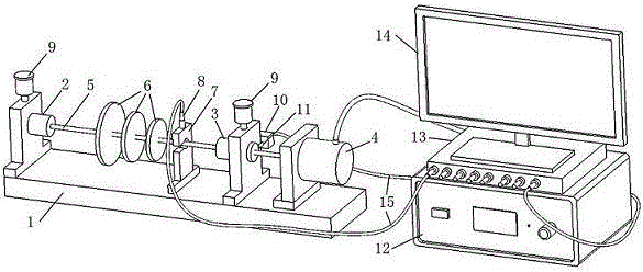
[0016] The symbols in the figure are: 1. Chassis 2. First sliding bearing 3. Second sliding bearing 4. Drag motor 5. Steam turbine rotor simulation main shaft 6. Steam turbine rotor simulation wheel 7. Displacement sensor bracket 8. Displacement sensor 9. Oil Pot 10. Speed ​​sensor bracket 11. Speed ​​sensor 12. Speed ​​governor 13. Vibration data analyzer 14. Computer and test software 15. Connecting wires

[0017] Its structure and composition are: chassis, first sliding bearing, second sliding bearing, drag motor, steam turbine rotor simulation main shaft, steam turbine rotor simulation wheel, displacement sensor bracket, displacement sensor, oil pot, speed sensor bracket, speed sensor, Speed ​​governor, vibration data analyzer, computer and test software, connecting wire. Install the first sliding bearing (2), the second slid...


PUM


Abstract

An experimental method for measuring critical speed influencing factor for a steam turbine rotor relates to an experimental apparatus and method for measuring critical speed related influencing factors for a steam turbine rotor. A first sliding bearing (2), a second sliding bearing (3), a drive motor (4), a displacement sensor support (7) and a speed sensor support (10) are mounted on a carriage (1), a steam turbine rotor simulation spindle (5) and a steam turbine rotor simulation wheel (6) are mounted on the above-mentioned two bearings, a displacement sensor (8) and a speed sensor (11) are fixed on a support, a measurement signal is processed in a vibration data analyzer (13) and input to a computer and test software (14), and a speed regulator (12) controls output speed of the drive motor (4) through a connecting wire (15). It is possible to measure changes in the critical speed of the rotor by changing structural rigidity and quality of the steam turbine simulation rotor, thus acquiring main factors that influence the critical speed of the steam turbine rotor and their effect.

Description

technical field [0001] The invention relates to an experimental measurement method for a steam turbine rotor, in particular to an experimental method for measuring the influencing factors of the critical rotational speed of the steam turbine rotor. Background technique [0002] Today's thermal power plants are developing towards the trend of large capacity and high parameters, and the requirements for stable operation and centralized control of units are very high. The steam turbine generator set is the core equipment of the thermal power plant, and its operation reliability will directly affect the safety and economy of the whole plant. The steam turbine rotor system is composed of main shaft, impeller, blades and couplings. The gap between the rotor system and the static part of the steam turbine is very small. During the operation, due to vibration, the unit will be rubbed, causing equipment damage. Excessive vibration will cause the unit to be damaged. downtime. Since ...

Claims


Application Information

Patent Timeline
Patent Type & Authority Applications(China)
IPC IPC(8): G01M15/00G01P3/00
CPCG01M15/00G01P3/00
Inventor 不公告发明人
Owner SHENYANG INST OF ENG
Learn More