Main circuit of traction converter for high-speed motor train unit

A technology for traction converters and high-speed EMUs, applied in electrical components, electronic commutation motor control, multiple motor speed/torque control, etc. High loss and other problems, to achieve the effect of reducing damage, good reliability, and reducing total loss

Active Publication Date: 2016-07-27
CRRC YONGJI ELECTRIC CO LTD
View PDF7 Cites 6 Cited by
  • Summary
  • Abstract
  • Description
  • Claims
  • Application Information

AI Technical Summary

Problems solved by technology

[0003] In order to optimize the problems of large calorific value, high heat loss, high IGBT cost and high counter electromotive force generated by the permanent magnet synchronous motor when being dragged, the present invention provides A main circuit of traction converter for high-speed EMU

Method used


Image

  • Main circuit of traction converter for high-speed motor train unit
  • Main circuit of traction converter for high-speed motor train unit
  • Main circuit of traction converter for high-speed motor train unit

Examples


Embodiment Construction

[0021] The present invention will be further described in detail below in conjunction with the accompanying drawings.

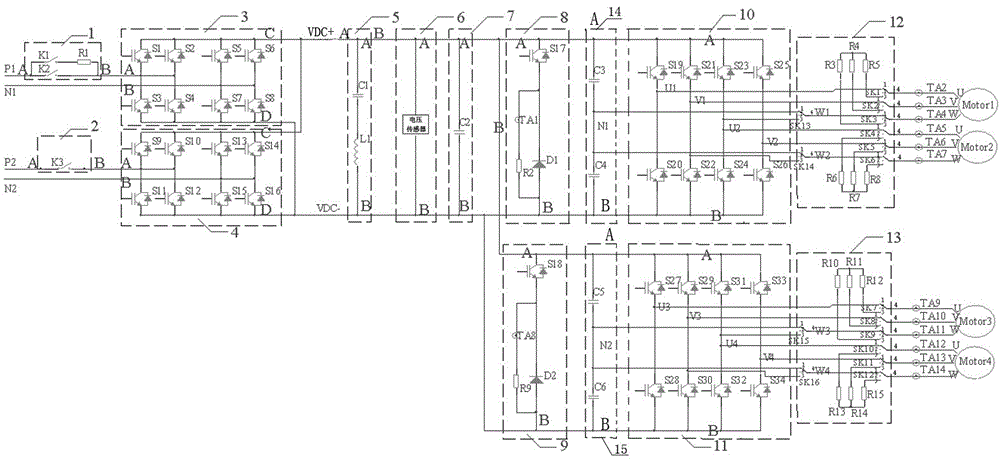
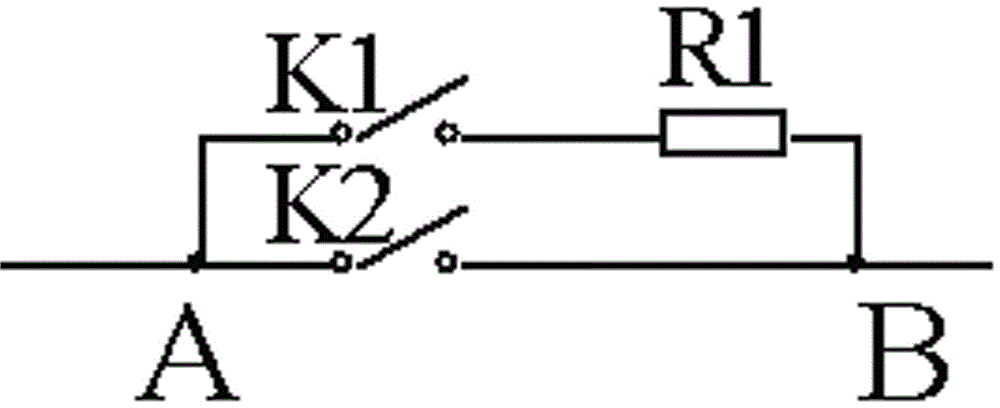
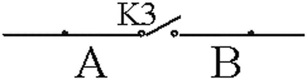
[0022] Such as figure 1 As shown, a high-speed EMU traction converter main circuit includes a first input voltage and current buffer circuit 1, a second input voltage and current buffer circuit 2, a first four-quadrant rectifier 3, a second four-quadrant rectifier 4, Secondary filter circuit 5, voltage sensor 6, support capacitor 7, first chopper circuit 8, second chopper circuit 9, first inverter 10, second inverter 11, first contactor circuit 12, second Two contactor circuits 13 , a first capacitor circuit 14 and a second capacitor circuit 15 .

[0023] The secondary side output winding P1 of the traction transformer is connected to the A terminal of the first voltage and current buffer circuit 1, the B terminal of the first voltage and current buffer circuit 1 is connected to the A terminal of the first four-quadrant rectifier 3, and the secondary side ou...


PUM


Abstract

The invention relates to a traction conversion device of a motor train unit, in particular to a main circuit of a traction converter for a high-speed motor train unit. The main circuit of the traction converter of the high-speed motor train unit comprises a first input voltage/current buffer circuit, a second input voltage/current buffer circuit, a first four-quadrant rectifier, a second four-quadrant rectifier, a secondary filter circuit, a voltage sensor, a support capacitor, a first chopping circuit, a second chopping circuit, a first inverter, a second inverter, a first contactor circuit, a second contactor circuit, a first capacitance circuit and a second capacitance circuit. The main circuit of the traction converter of the high-speed motor train unit, proposed by the invention, has the advantages of energy saving, low heat generation, high protection capability, high reliability and the like, is applicable to various mode running, and the problems of high heat generation, high thermal loss and high cost of the converter of the existing permanent-magnet synchronous motor are solved.

Description

technical field [0001] The invention relates to a traction converter for a train set, in particular to a main circuit of a traction converter for a high-speed train set. Background technique [0002] The traction converter is an important part of the high-speed EMU. The main function of the traction converter is to drive the motor to drive the operation of the EMU. Permanent magnet synchronous motor is a kind of AC motor, and has been widely used in various industries due to its high power density, fast response, low loss and other advantages, and has been applied to the field of rail transit. However, the main circuit of the existing traction converter for driving permanent magnet synchronous motors mostly uses 3-phase bridge arms to control one permanent magnet synchronous motor, and 12 bridge arms and 24 IGBTs are required to control 4 motors, resulting in large heat generation of the converter , high heat loss and high cost. The permanent magnet synchronous motor will ...

Claims


Application Information

Patent Timeline
Patent Type & Authority Applications(China)
IPC IPC(8): H02P6/04H02P6/182
CPCH02P6/04H02P6/182
Inventor 张瑞峰詹哲军李岩李国锋张桂成
Owner CRRC YONGJI ELECTRIC CO LTD
Why Eureka
Try Eureka