Clock duty ratio adjusting circuit

A technology to adjust the circuit and duty cycle, which is applied in the direction of electrical components, generating electric pulses, and electric signal transmission systems, etc. It can solve the problems of inability to guarantee the stability of the clock signal duty cycle, affecting clock jumps and inversions, and functional errors. To achieve the effect of simplifying the signal output path, speeding up the start-up process, and offsetting errors

Active Publication Date: 2016-07-27
58TH RES INST OF CETC
View PDF3 Cites 26 Cited by
  • Summary
  • Abstract
  • Description
  • Claims
  • Application Information

AI Technical Summary

Problems solved by technology

[0003] Because the clock signal is affected by the signal attenuation on the transmission line, the mutual interference of other signals, the threshold fluctuation of the inverter transistor caused by the process, and the deviation of the rising and falling edges during the propagation process, the clock circuit of the high-speed pipeline ADC cannot guarantee the stability of the clock signal duty cycle.
In the process of high-frequency signal processing, the accumulative effect of clock misalignment in the transmission link makes the duty cycle misalignment worsen, affecting the normal jumping and flipping of the clock, causing timing disorder, functional error and even failure

Method used


Image

  • Clock duty ratio adjusting circuit
  • Clock duty ratio adjusting circuit
  • Clock duty ratio adjusting circuit

Examples


Embodiment Construction

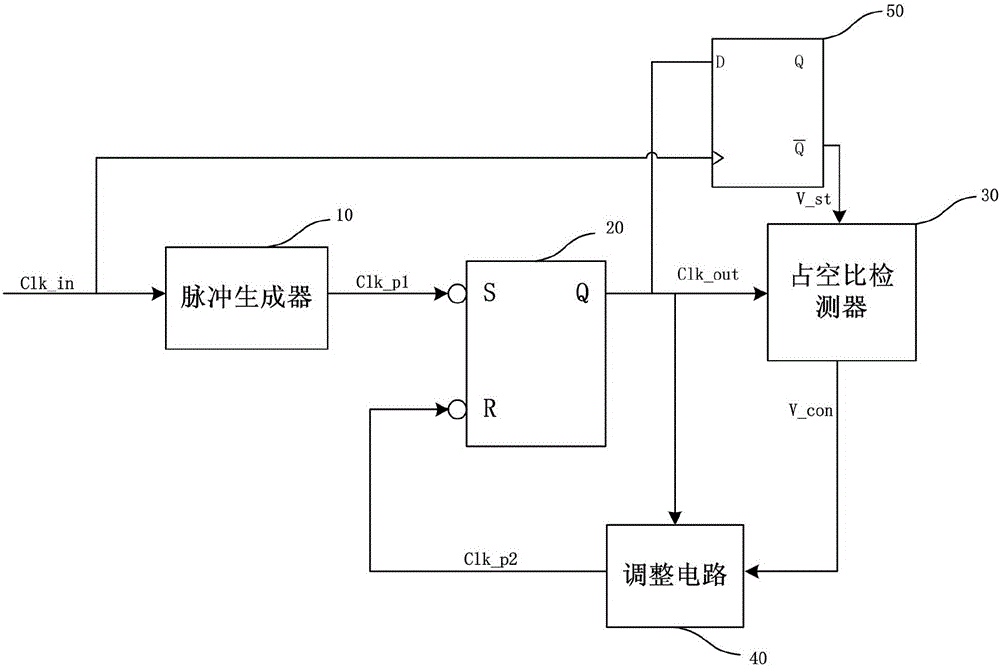
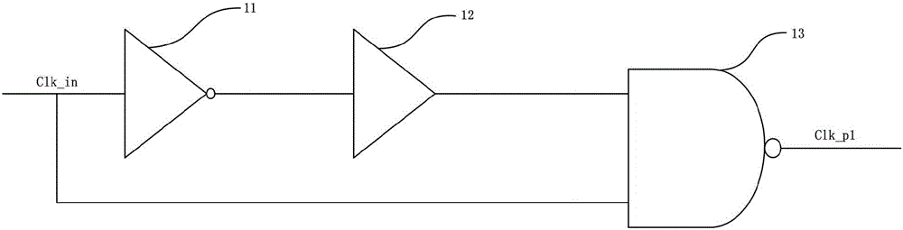
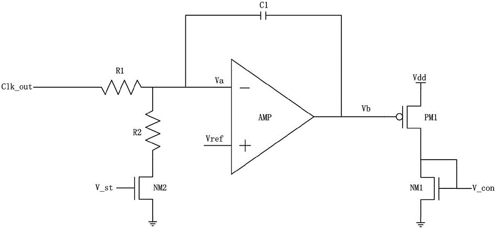
[0017] Such as Figure 1 to Figure 5 As shown, a clock duty ratio adjustment circuit according to the present invention includes a pulse generator 10 , an RS flip-flop 20 , a duty ratio detector 30 , an adjustment circuit 40 and a D flip-flop 50 . The pulse generator 10, the RS flip-flop 20 and the adjustment circuit 40 are connected in sequence. The output terminal of the pulse generator 10 is connected with the S input terminal of the RS flip-flop 20 . The output terminals of the RS flip-flop 20 are respectively connected with the input terminals of the D flip-flop 50 , the duty ratio detector 30 and the adjustment circuit 40 . The inverting output terminal of the D flip-flop 50 is connected with the input terminal of the duty cycle detector 30 . The output terminal of the duty ratio detector 30 is connected with the input terminal of the adjustment circuit 40 . The output terminal of the adjustment circuit 40 is connected with the R input terminal of the RS flip-flop 20 ...


PUM


Abstract

The invention relates to a clock duty ratio adjusting circuit. The clock duty ratio adjusting circuit comprises a pulse generator, an RS trigger, a duty ratio detector, an adjusting circuit and a D trigger. The pulse generator, the RS trigger and the adjusting circuit are successively connected. The pulse generator is connected to the S input end of the RS trigger; the output end of the RS trigger is connected respectively to the D trigger, the duty ratio detector and the input end of the adjusting circuit; the anti-phase output end of the D trigger is connected to the input end of the duty ratio detector; the output end of the duty ratio detector is connected to the input end of the adjusting circuit; the output end of the adjusting circuit is connected to the R input end of the RS trigger; inputted clock signals are accessed into the pulse generator and the D trigger. According to the invention, an RS trigger is adopted to integrate the edges of a clock. The paths of the duty ratio detector and the adjusting circuit are separate from their output path. The signal outputting path is rather simplified and features low shaking characteristics. The adoption of integrator negative feedback continuous time adjusting enables high accuracy.

Description

technical field [0001] The invention belongs to the technical field of clock circuit design in integrated circuits, and in particular relates to a clock duty ratio adjustment circuit. Background technique [0002] At present, with the continuous development of integrated circuit technology, as the mainstream structure of high-speed and high-precision ADCs, the accuracy and speed that can be realized by pipeline-structured ADC circuits continue to increase. However, the data conversion process of each sub-stage circuit in the pipeline ADC circuit structure inevitably needs to be controlled by two-phase non-overlapping clocks. The stage circuit conversion has sufficient settling time and the highest clock utilization efficiency. The 50% duty cycle clock can not only realize the stable operation of the high-speed pipeline ADC system, but also achieve the best conversion performance. [0003] Because the clock signal is affected by the signal attenuation on the transmission lin...

Claims


Application Information

Patent Timeline
Patent Type & Authority Applications(China)
IPC IPC(8): H03K3/017H03M1/54
CPCH03K3/017H03M1/54
Inventor 魏敬和朱晓宇戴强
Owner 58TH RES INST OF CETC
Why Eureka
Try Eureka