Cleaning machine for cylinder barrel of oil cylinder

A cleaning machine and cylinder technology, which is applied in the directions of cleaning hollow objects, cleaning methods and utensils, chemical instruments and methods, etc., can solve problems such as poor cleaning effect of oil tanks, achieve high cleaning efficiency, reduce sewage discharge, and good cleaning effect. Effect

Active Publication Date: 2016-08-03
江苏昊阳传动科技有限公司
View PDF7 Cites 3 Cited by
  • Summary
  • Abstract
  • Description
  • Claims
  • Application Information

AI Technical Summary

Problems solved by technology

[0005] In order to overcome the poor cleaning effect of the oil cylinder in the prior art and the need to separate the internal and external cleaning into multiple processes, the present invention provides an oil cylinder barrel cleaning machine

Method used


Image

  • Cleaning machine for cylinder barrel of oil cylinder
  • Cleaning machine for cylinder barrel of oil cylinder
  • Cleaning machine for cylinder barrel of oil cylinder

Examples


Embodiment Construction

[0025] The present invention will be described in further detail below in conjunction with the accompanying drawings and embodiments. It should be understood that the specific embodiments described here are only used to explain the present invention, not to limit the present invention.

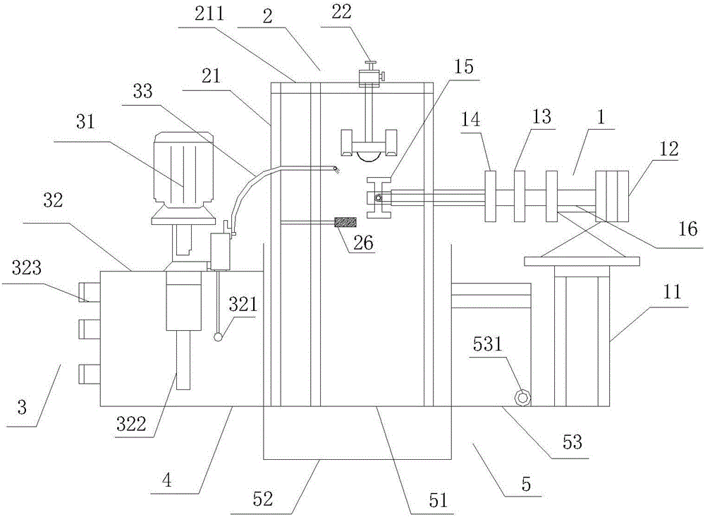
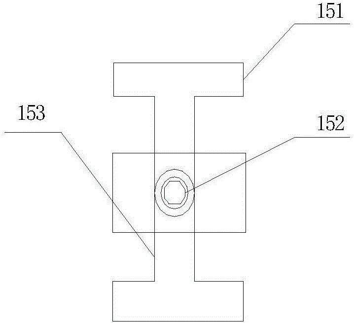
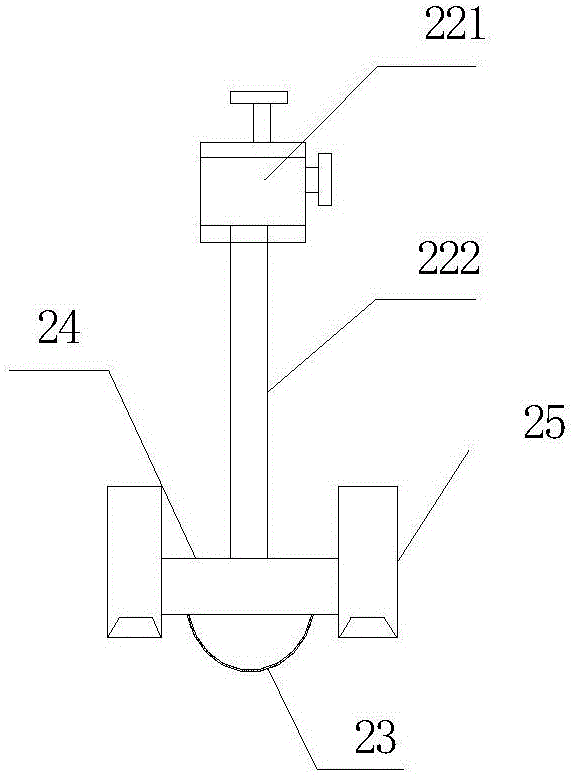
[0026] Such as figure 1 , figure 2 , image 3 and Figure 4 , this specific embodiment discloses an oil cylinder barrel cleaning machine, including a driving part 1, a cleaning part 2, a cleaning liquid supply part 3, a base 4 and a sewage collection and treatment device 5, the driving part 1 and the cleaning liquid supply part 3 Located on both sides of the cleaning part 2, the driving part 1, the cleaning part 2, the cleaning liquid supply part 3 and the sewage collection and treatment device 5 are respectively located on the upper end of the base 4 and fixedly connected to it by welding. The sewage collection and treatment device 5 is located directly below the cleaning part 2. Brush ...


PUM


Abstract

The invention provides a cleaning machine for a cylinder barrel of an oil cylinder. The cleaning machine comprises a drive part, a cleaning part, a cleaning liquid supply part, a base and a sewage collecting and treating device. The drive part and the cleaning liquid supply part are located on the two sides of the cleaning part correspondingly. The drive part, the cleaning part, the cleaning liquid supply part and the sewage collecting and treating device are located at the upper end of the base and fixedly connected with the base. The sewage collecting and treating device is located under the cleaning part. The cleaning part comprises a stand column, a cleaning brush telescopic device, a spherical cleaning brush, a fixed trough, drying devices and an inner cleaning brush. The stand column is fixedly connected with the base. The cleaning brush telescopic device is fixedly connected with the upper end of the stand column. The spherical cleaning brush and the fixed trough are located at the lower end of the cleaning brush telescopic device and fixedly connected with the cleaning brush telescopic device. The spherical cleaning brush is located in the fixed trough and movably connected with the fixed trough. The drying devices are located on the two sides of the fixed trough and fixedly connected with the fixed trough. The inner cleaning brush is fixedly connected with the stand column. The cleaning machine is high in cleaning efficiency and good in cleaning effect.

Description

technical field [0001] The invention relates to the technical field of structural design of cleaning equipment, in particular to an oil cylinder cylinder cleaning machine. Background technique [0002] The hydraulic cylinder is a linear motion actuator whose output force is proportional to the effective area of ​​the piston and the pressure difference on both sides. Its function is to convert hydraulic energy into mechanical energy. The input of the hydraulic cylinder is the flow and pressure of the fluid, and the output is the linear motion speed and force. The piston of the hydraulic cylinder can complete linear reciprocating motion, and the output linear displacement is limited. A hydraulic cylinder is an energy conversion device that converts hydraulic energy into mechanical energy for reciprocating linear motion. The basic feature of the cylinder is deep hole processing, and its processing and cleaning have always troubled the processors, especially the cleaning of t...

Claims


Application Information

Patent Timeline
Patent Type & Authority Applications(China)
IPC IPC(8): B08B9/30B08B9/36
CPCB08B9/30B08B9/36
Inventor 周建伟钱新锋蔡连富
Owner 江苏昊阳传动科技有限公司
Why Eureka
Try Eureka