
Automobile wheel inertial energy hydraulic recovery and comprehensive utilization system and control method thereof

An inertial energy and hydraulic technology, applied in the direction of control devices, brakes, brake components, etc., can solve problems such as restricting application and promotion, affecting transmission efficiency, and high manufacturing costs, achieving small structural changes, high transmission efficiency, and low cost. not high effect

Active Publication Date: 2016-08-03
JIANGSU UNIV
View PDF8 Cites 10 Cited by
  • Summary
  • Abstract
  • Description
  • Claims
  • Application Information

AI Technical Summary

Problems solved by technology

[0003] Using the flywheel to recover and store the inertial energy of the car is a common way at present. In order to maintain the continuous operation of the flywheel, the flywheel needs to be installed in a vacuum environment without wind resistance. In order to eliminate the frictional resistance of the bearing rotation, a magnetic levitation support system is required. Due to the The matching vacuum generating device and air source equipment not only have a complex structure, take up a lot of space, but also have high manufacturing costs. In addition to the supporting vacuum pump, the air pump itself consumes energy, which affects and restricts the application and promotion of this technology
[0004] At present, many existing energy recovery devices have complex structures, all of which use indirect transmission, and the transmission chain is long, which affects the transmission efficiency.

Method used


Image

  • Automobile wheel inertial energy hydraulic recovery and comprehensive utilization system and control method thereof
  • Automobile wheel inertial energy hydraulic recovery and comprehensive utilization system and control method thereof
  • Automobile wheel inertial energy hydraulic recovery and comprehensive utilization system and control method thereof

Examples


Embodiment Construction

[0038] The present invention will be further described below in conjunction with the accompanying drawings and specific embodiments, but the protection scope of the present invention is not limited thereto.

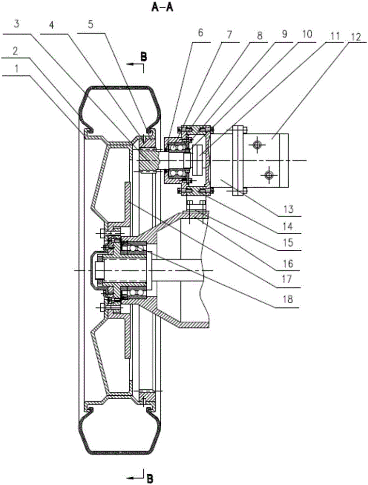
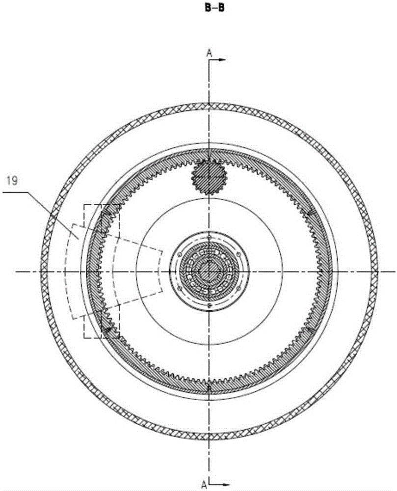
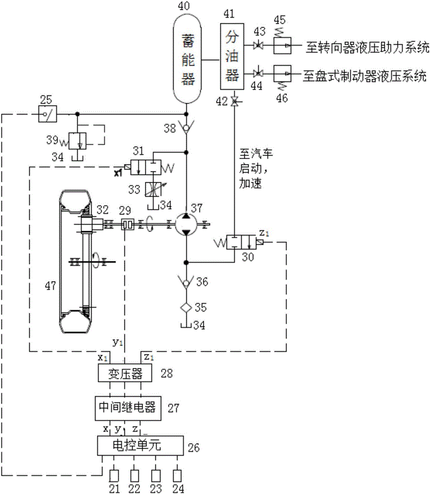
[0039] Said hydraulic recovery and comprehensive utilization system of the inertial energy of automobile wheels, an internal gear insert 5 or an internal gear pressure fitting is added and fixed on the inner ring of the automobile wheel hub, and an internal gear transmission mechanism is installed above the automobile bridge body, Install electromagnetic clutch and hydraulic pump / hydraulic motor on the same transmission shaft. When the wheels of the car rotate, the power passes through the internal gear transmission mechanism, and the electromagnetic clutch directly drives the hydraulic pump / hydraulic motor to work. When the car brakes, decelerates, and coasts, the hydraulic energy generated by the hydraulic pump drive mode is input into the accumulator; when the car star...


PUM


Abstract

The present invention provides an automobile wheel inertial energy hydraulic recovery and comprehensive utilization system and a control method thereof, belonging to the technical field of energy conservation and emission reduction of automobiles. An inner gear ring is additionally arranged and fixed on an automobile hub, when automobile wheels rotate, power passes an inner gear transmission mechanism for acceleration, to directly drive a hydraulic pump / hydraulic motor to work. When the automobile is braked, is subjected to deceleration and slides, the inertial energy of the wheels is quickly largely converted into hydraulic energy to be stored, and when the automobile is started and is subjected to acceleration, the stored hydraulic energy is converted into mechanical energy to be directly provided for the wheels. The hydraulic energy in an energy accumulator can be applied to an automobile steering device hydraulic power assisted system or a disc brake hydraulic system by selecting the switching modes. The device is simple in structure, small in size, high in energy recovery rate and low in manufacturing cost, and has a certain technical and economic feasibility.

Description

technical field [0001] The invention relates to a hydraulic recovery and comprehensive utilization system of automobile inertia energy, which belongs to the technical field of automobile energy saving and emission reduction. Background technique [0002] When the car is running on the road, the energy generated by the fuel engine or the driving motor of the electric car is not only used to overcome the resistance of the air, but its main energy is used to overcome the rolling resistance of the car wheels. The main factors affecting the resistance of this part are The weight of the car and the speed at which it is traveling. When the car brakes, decelerates and slides downhill, it will generate huge kinetic energy and potential energy. For example, a car with a self-weight of 2000kg and a speed of 80km / h, according to calculations, it stores about 493kJ of kinetic energy. If the kinetic energy is recovered for 30 %, the car can continue to travel for about 1 kilometer. There...

Claims


Application Information

Patent Timeline
IPC IPC(8): B60K25/08B60T1/10
CPCB60K25/08B60T1/10
Inventor 汪若尘邵凯叶青陈龙江浩斌
Owner JIANGSU UNIV
Learn More