Oil-water separating device, and oil sludge separating apparatus including same

A technology of oil-water separation device and heat exchange device, which is applied in dehydration/drying/concentrated sludge treatment, grease/oily substance/float removal device, liquid separation, etc., can solve resource waste, low oil and gas recovery efficiency, and environmental pollution and other problems, to avoid sucking back, improve condensation efficiency, and improve recovery efficiency.

Inactive Publication Date: 2016-08-03
BEIJING INST OF AEROSPACE TESTING TECH +1
View PDF12 Cites 6 Cited by
  • Summary
  • Abstract
  • Description
  • Claims
  • Application Information

AI Technical Summary

Problems solved by technology

Although the invention improves the efficiency of oil-water separation, when the high-temperature oil-water mixture enters the shell, the gaseous oil and gas are difficult to collect on the corrugated plate, so that most of the oil and gas escape from the corrugated plate along with the air that is difficult to dissolve in water. The collected oil and gas not only pollutes the environment but also greatly reduces the recovery efficiency of the equipment, and the recovery effect is not ideal
[0003] Most of the existing sludge separation equipment adopts traditional oil-water separation devices. After the separated high-temperature oil-water mixture enters the oil-water separation device, the recovery efficiency of oil and gas is low, and some oil and gas are not condensed effectively and are directly discharged into the atmosphere. It not only causes a waste of resources, but also pollutes the environment. Therefore, effectively improving the condensation recovery efficiency of oil and gas is the key to improving the efficiency of the entire sludge separation equipment.

Method used


Image

  • Oil-water separating device, and oil sludge separating apparatus including same
  • Oil-water separating device, and oil sludge separating apparatus including same
  • Oil-water separating device, and oil sludge separating apparatus including same

Examples


Embodiment 1

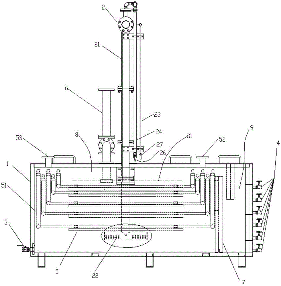
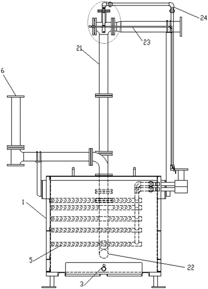
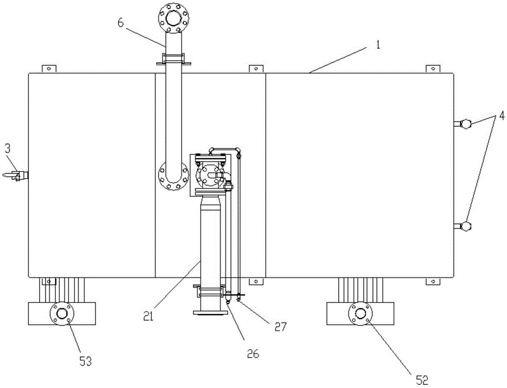
[0036] combine figure 1 and Figure 5 As shown, an oil-water separation device includes a housing 1 for holding liquid oil and water, an oil inlet device 2 arranged on the housing 1, a drain 3 located on one side of the bottom of the housing 1 and a water outlet located on the other side. A plurality of oil outlets 4 on the side, and a heat exchange device 5 arranged in the housing 1 for cooling the liquid contained in the housing 1, the heat exchange device 5 includes a multi-layer heat exchange tube 51, and the heat exchange tube 51 is connected to Condensed water is used to reduce the temperature in the casing 1 . The oil inlet device 2 includes an oil inlet pipeline 21 connected to the housing 1 and a cooling device arranged in the oil inlet pipeline 21 for condensing high-temperature oil-water mixture, the cooling device is preferably a spray cooling device, Cool the high-temperature oil-water mixture by spraying condensed water. One end of the oil inlet pipe 21 inside...

Embodiment 2

[0044] Such as Figure 6 As shown, the difference between the present embodiment and the first embodiment is that: the middle part of the short pipe 22 is rotatably connected with the oil inlet pipe 21 and communicated with each other, and the two ends of the short pipe are closed. The short pipe 22 is rotatably connected to the bottom of the oil inlet pipeline 21, and the two are connected by a rotary joint 28. The nozzles are arranged on the side wall of the short pipe 22 and distributed on different sides of the short pipe 22, and to further The axis of the oil pipeline 21 is centered and symmetrically arranged. After the high-temperature gas is ejected from the nozzle, it generates a reaction force that pushes the short pipe 22 to rotate. The rotation of the short pipe 22 makes the bubbles ejected from the nozzle more uniform and larger. The dispersion area is in contact with the condensed water in the housing 1 to achieve a better condensation effect.

[0045] Such as ...


PUM


Abstract

The invention relates to an oil-water separating device and an oil sludge separating apparatus including the same. The oil-water separating device comprises a shell, an oil feeding unit arranged on the shell, a drainage hole, an oil outlet and a heat exchange unit arranged in the shell, wherein the heat exchange unit comprises multiple layers of heat exchange tubes, the oil feeding unit comprises an oil feeding pipeline communicated with the interior of the shell, the end , located in the shell, of the oil feeding pipeline is provided with a plurality of nozzles, and the nozzles are located among the heat exchange tubes or below the heat exchange tubes. The oil-water separating device provided by the invention has good condensation effect, can effectively reduce the temperature of high-temperature oil gas, greatly improves oil-water separation efficiency, enhances the utilization rate of waste oil, and achieves the purposes of energy conservation and environmental protection.

Description

technical field [0001] The invention relates to a sludge treatment equipment, in particular to an oil-water separation device and the sludge separation equipment containing the device. Background technique [0002] Most of the existing oil-water separation devices are used to separate the liquid oil-water mixture. Since the liquid oil-water mixture generally has a relatively low temperature, it only needs to use the difference in oil-water density to separate. The Chinese invention patent with the authorized notification number CN102266680B discloses a kind of oil-water separator, which includes a housing, an oil outlet device, and an oil phase collector. The housing is provided with a feed pipe and a water outlet. The oil phase collector is composed of multiple The corrugated plates are composed of corrugated plates, and the corrugated plates are superimposed and fixed into one body, so that several channels are formed between the adjacent corrugated plates. An oil collect...

Claims


Application Information

Patent Timeline
Patent Type & Authority Applications(China)
IPC IPC(8): C02F1/40C02F11/12
Inventor 路兰卿许鸿昊许健刘平李亚鹏孙拥军成清校程潮李喜白宇
Owner BEIJING INST OF AEROSPACE TESTING TECH
Why Eureka
Try Eureka