Integrated Pit Tunnel Boring Machine

A tunnel boring machine, an integrated technology, applied in tunnels, mining equipment, earthwork drilling and mining, etc., can solve problems such as low construction efficiency, easy wear, and reduced construction efficiency, so as to improve tunneling efficiency, reduce manufacturing costs, and reduce preparation costs. cost effect

Active Publication Date: 2019-06-18
四川福隧科技有限公司
View PDF6 Cites 1 Cited by
  • Summary
  • Abstract
  • Description
  • Claims
  • Application Information

AI Technical Summary

Problems solved by technology

But in the actual excavation process, there are still many deficiencies as follows: 1. The drilling mechanism, the sawing mechanism and the vault forming mechanism are all independent mechanisms. →The drilling mechanism exits → the sawing mechanism enters the sawing → the sawing mechanism exits → the vault forming mechanism enters the construction → the vault forming mechanism exits" such a construction process cycle construction, there are complex construction procedures and low construction efficiency Defects
2. The entire roadheader requires the cooperation of three sets of independent mechanisms to complete the construction of the pit tunnel, which requires the manufacture of three sets of independent equipment, resulting in extremely high manufacturing costs for the entire roadheader
3. The vault forming mechanism adopts the structure of the saw blade group to form the vault, and the saw blade group is easy to wear when cutting the rock mass, which further increases the excavation cost of the pit tunnel
4. During excavation, the three sets of equipment are constructed alternately according to the process, but the next set of equipment needs to be calibrated before construction. For example, after the drilling mechanism drills, the sawing mechanism needs to be calibrated with the drilled hole before entering construction. It will inevitably lead to a significant reduction in construction efficiency.
5. In order to ensure the stability and accuracy of the excavation, the three sets of independent equipment are equipped with three sets of slow-speed travel systems, but the slow-speed travel system also leads to slow entry and exit speeds of the three sets of equipment, which also affects the construction efficiency

Method used


Image

  • Integrated Pit Tunnel Boring Machine
  • Integrated Pit Tunnel Boring Machine
  • Integrated Pit Tunnel Boring Machine

Examples


Embodiment 1

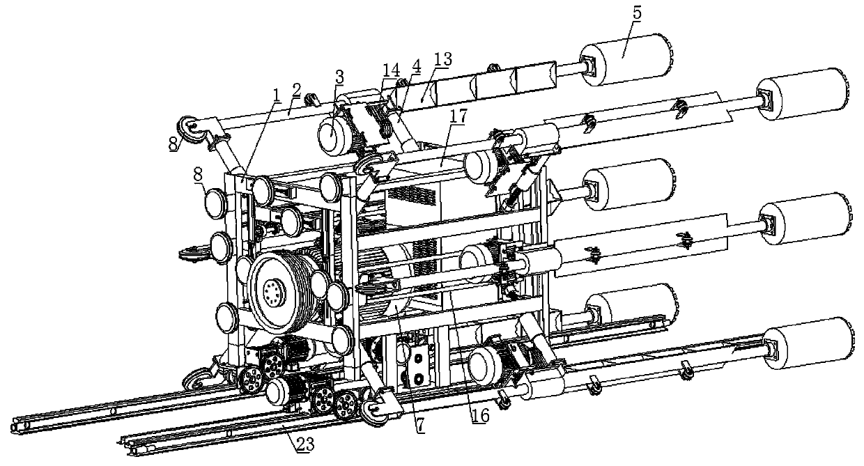
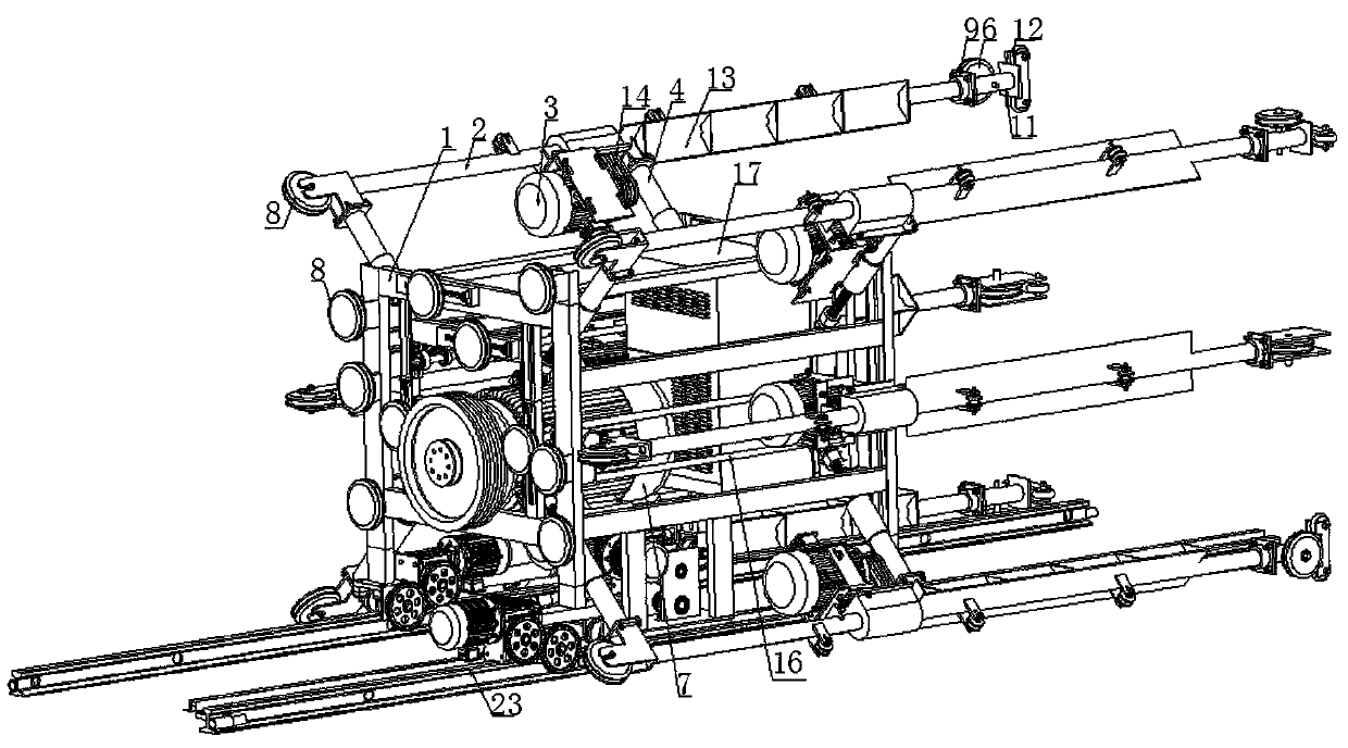
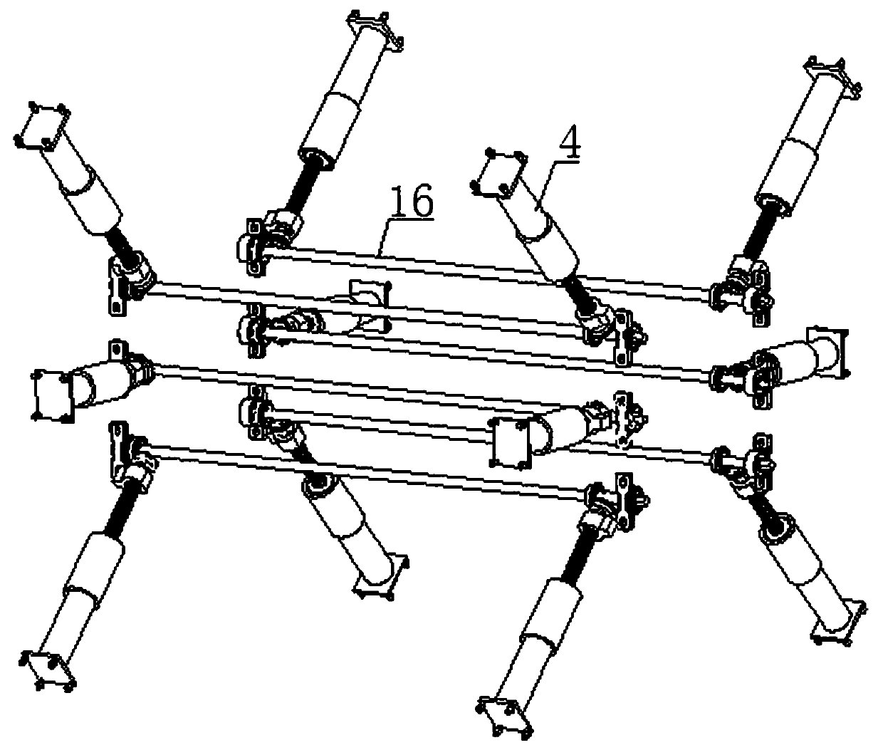
[0046] An integrated pit tunnel boring machine, including a frame 1 and a drilling and sawing mechanism, the drilling and sawing mechanism includes an arm 2, a transmission shaft, a drive motor 3, a telescopic seat 4, a drill barrel 5, and a cutting wheel 6 , main motor 7, saw rope and a plurality of guide wheels 8, the drive motor 3, main motor 7, telescopic seat 4 and a plurality of guide wheels 8 are all fixed on the frame 1, and the arm bar 2 is fixed on the telescopic seat 4, the transmission shaft is sleeved in the arm 2, and the driving motor 3 is connected with the transmission shaft in the arm 2 through a belt 14; when drilling, the drill tube 5 is fixed on the end of the transmission shaft, and the driving motor 3 Drive the drill cylinder 5 to work through the transmission shaft; when sawing, the cutting wheel 6 is movably arranged at the end of the arm bar 2, and the main motor 7 drives the cutting wheel 6 to work through the saw rope and a plurality of guide wheels ...

Embodiment 2

[0055] This embodiment is basically the same as Embodiment 1, the main difference is that: the drive motor 3 is connected to the transmission shaft through the gear transmission gearbox 15 , that is, the drive motor 3 drives the transmission shaft to rotate through the gear transmission transmission gearbox 15 .

Embodiment 3

[0057] An integrated pit tunnel boring machine, including a frame 1 and a drilling and sawing mechanism, the drilling and sawing mechanism includes an arm 2, a transmission shaft, a drive motor 3, a telescopic seat 4, a drill barrel 5, and a cutting wheel 6 , main motor 7, saw rope and a plurality of guide wheels 8, the drive motor 3, main motor 7, telescopic seat 4 and a plurality of guide wheels 8 are all fixed on the frame 1, and the arm bar 2 is fixed on the telescopic seat 4, the transmission shaft is sleeved in the arm 2, and the driving motor 3 is connected with the transmission shaft in the arm 2 through a belt 14; when drilling, the drill tube 5 is fixed on the end of the transmission shaft, and the driving motor 3 Drive the drill cylinder 5 to work through the transmission shaft; when sawing, the cutting wheel 6 is movably arranged at the end of the arm bar 2, and the main motor 7 drives the cutting wheel 6 to work through the saw rope and a plurality of guide wheels ...


PUM


Abstract

The invention discloses an integrated pit tunnel heading machine which comprises a rack and a drilling sawing mechanism, wherein the drilling sawing mechanism comprises arm levers, transmission shafts, driving motors, telescopic seats, drilling barrels, cutting wheels, a main motor, saw ropes and a plurality of guide wheels; the driving motors, the main motor, the telescopic seats and the plurality of guide wheels are all fixed on the rack; the arm levers are fixed on the telescopic seats; the transmission shafts are sleeved with the arm levers; the driving motors are connected with the transmission shafts in the arm levers; in the drilling process, the drilling barrels are fixed at the end parts of the transmission shafts, and the driving motors drive the drilling barrels to work by the transmission shafts; in the sawing process, the cutting wheels are movably arranged at the end parts of the arm levers, and the main motor drives the cutting wheels to work by the saw ropes and the plurality of guide wheels. The integrated pit tunnel heading machine disclosed by the invention solves the technical problems that a drilling mechanism and a sawing mechanism in an existing rope saw type heading machine are combined into one whole body; in the process of heading a pit tunnel, equipment does not need to enter and exit in a reciprocating manner; equipment calibration is reduced; heading of the pit tunnel can be rapidly implemented.

Description

technical field [0001] The invention relates to the technical field of pit tunnel excavation, in particular to an integrated pit tunnel boring machine. Background technique [0002] In the excavation of tunnels or tunnels, the commonly used measures are blasting excavation or shield machine excavation. Among them, there are serious safety hazards in blasting excavation, and the construction quality is difficult to guarantee. The phenomenon of over-excavation and under-excavation is very prominent. When crossing areas with complex geological conditions, the safety risks are multiplied, so its use is very cautious. Shield machine excavation is the use of shield machine equipment for excavation. Shield machine equipment integrates optical, mechanical, electrical, hydraulic, sensing, and information technologies. It has the functions of excavating and cutting soil, conveying soil, and assembling tunnel lining , measurement-oriented correction and other functions, but due to its...

Claims


Application Information

Patent Timeline
Patent Type & Authority Patents(China)
IPC IPC(8): E21D9/10
CPCE21D9/1006
Inventor 张清林
Owner 四川福隧科技有限公司
Why Eureka
Try Eureka