Method of operating internal combustion engine

A technology for internal combustion engines and fuel rails, applied in engine control, engine components, machines/engines, etc., can solve problems such as application, and achieve the effect of low computing workload

Inactive Publication Date: 2016-08-03
GM GLOBAL TECH OPERATIONS LLC
View PDF5 Cites 7 Cited by
  • Summary
  • Abstract
  • Description
  • Claims
  • Application Information

AI Technical Summary

Problems solved by technology

However, due to the structural design of fuel injectors (especially solenoid injectors), there is always a certain delay between the application of the energizing current and the actual opening of the fuel injector

Method used


Image

  • Method of operating internal combustion engine
  • Method of operating internal combustion engine
  • Method of operating internal combustion engine

Examples


Embodiment Construction

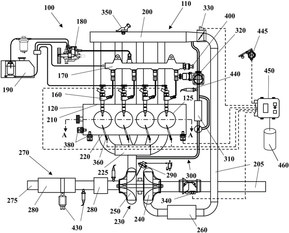
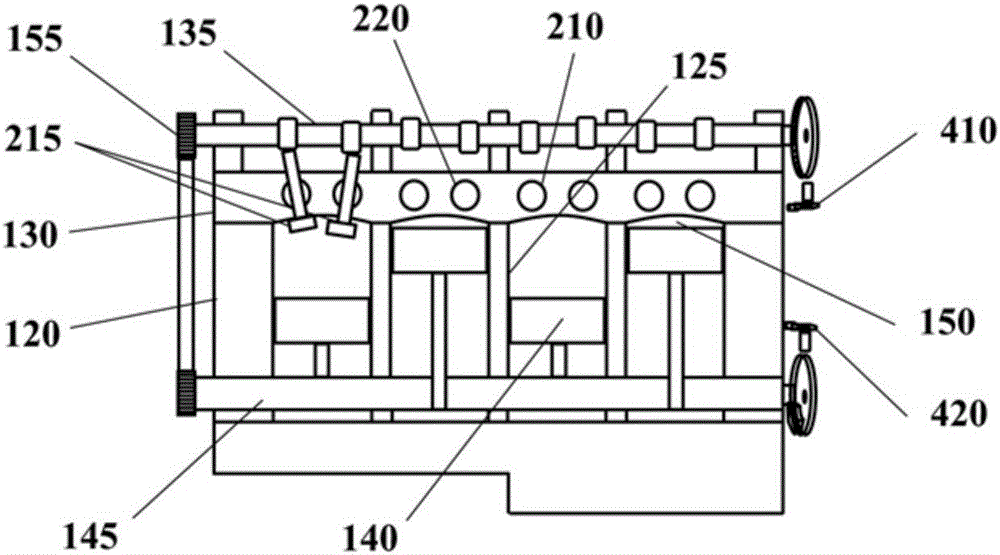
[0217] Some implementations may include such as figure 1 and figure 2 The illustrated automotive system 100 (e.g., a motor vehicle) includes an internal combustion engine (ICE) 110 having an engine block 120 defining at least one cylinder 125 with a crankshaft 145 coupled to Rotating piston 140 . Cylinder head 130 cooperates with piston 140 to define combustion chamber 150 . A fuel and air mixture (not shown) is disposed in combustion chamber 150 and is ignited, which produces thermally expanding exhaust gases causing reciprocation of piston 140 . Fuel is provided by at least one fuel injector 160 and air is provided through at least one intake port 210 for each combustion chamber. Fuel is provided to fuel injector 160 at high pressure from fuel rail 170 in fluid communication with high pressure fuel pump 180 that increases the pressure of fuel received from fuel source 190 .

[0218] The high-pressure fuel pump 180 may be implemented as a displacement pump having a cylin...


PUM


Abstract

Disclosed is a method of operating an internal combustion engine 110, wherein the internal combustion engine comprises a fuel rail 170 in fluid communication with a fuel pump 180 and with a fuel injector 160. The method comprises the steps of: operating the fuel injector to perform fuel injection and sampling a signal representative of a fuel pressure within the fuel rail during the fuel injection; using the pressure signal as an input of a first integral transform yielding as its output a value of a first function having as variables a fuel rail pressure drop caused by the fuel injection and a timing parameter indicative of an instant when the fuel injection started; using the pressure signal as an input of a second integral transform yielding as its output a value of a second function having as variables the fuel rail pressure drop caused by the fuel injection and the timing parameter indicative of the instant when the fuel injection started; using the value of the first function and the value of the second function to calculate a value of the fuel rail pressure drop caused by the fuel injection and a value of the timing parameter; and calculating s value of a fuel quantity injected by the fuel injection as a function of the value of the fuel rail pressure drop.

Description

technical field [0001] The present invention generally relates to a method of operating an internal combustion engine of a motor vehicle, such as a diesel engine or a gasoline engine. More particularly, the present invention relates to a method of determining the actual amount of fuel injected by a fuel injector of an engine and the time at which that fuel injection actually occurred. Background technique [0002] Internal combustion engines of known motor vehicles typically include a fuel injection system comprising a high pressure fuel pump delivering fuel at high pressure to a fuel rail and a plurality of fuel injectors in fluid communication with the fuel rail, the plurality of fuel injectors Each of the is configured to inject a metered amount of fuel into a corresponding combustion chamber of the engine. [0003] Conventionally, each fuel injector executes multiple injection pulses per engine cycle according to the multiple injection mode. This multi-injection patter...

Claims


Application Information

Patent Timeline
Patent Type & Authority Applications(China)
IPC IPC(8): F02D41/38F02D41/14
CPCF02D41/1486F02D41/2477F02D41/3809F02D41/402F02D2200/0616F02D2200/0602F02D41/3827F02D2200/0618F02M26/05F02M26/25F02M26/47F02D41/2467F02D2041/286F02D41/24F02D41/30F02D41/40F02D1/02
Inventor S.尼杜A.莫拉
Owner GM GLOBAL TECH OPERATIONS LLC
Why Eureka
Try Eureka