a gas burner

A gas burner, gas technology, applied in burners, gas fuel burners, combustion methods and other directions, can solve the problems of difficult cleaning, insufficient gas combustion, easy clogging of fire holes, etc., to improve uniformity and stability, The effect of sufficient gas combustion and improved combustion efficiency

Active Publication Date: 2017-05-03
NINGHAI JINING KITCHEN UTENSILS CO LTD
View PDF5 Cites 0 Cited by
  • Summary
  • Abstract
  • Description
  • Claims
  • Application Information

AI Technical Summary

Problems solved by technology

[0003] The gas mixing structure and the flame hole structure are two important structures that affect the use effect of the burner. The existing burner can basically meet the existing use requirements, but there are the following technical problems in the above two links: 1. The gas mixing process is relatively slow. Simple, generally one-time gas mixing, resulting in poor gas mixing effect, uneven mixing of gas and air, resulting in low combustion efficiency and serious environmental pollution; 2. The design of the fire hole is unreasonable, resulting in loud noise when the gas flows out, and the gas is stable The problem of poor performance leads to insufficient gas combustion, low combustion efficiency, easy blockage of the fire hole, difficult to clean, and, in the combustion process, prone to problems such as low heat intensity, tempering, and flame separation

Method used


Image

  • a gas burner
  • a gas burner
  • a gas burner

Examples


Embodiment Construction

[0047] The following are specific embodiments of the present invention and in conjunction with the accompanying drawings, the technical solutions of the present invention are further described, but the present invention is not limited to these embodiments.

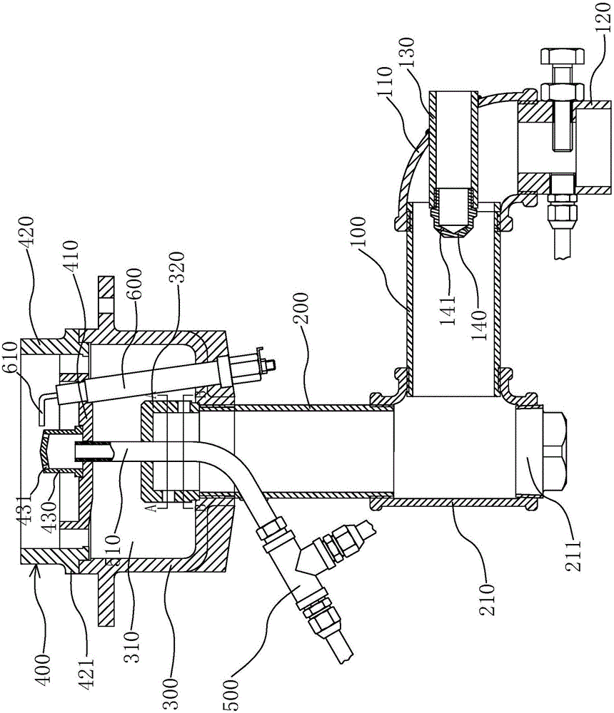
[0048] like figure 1 As shown, a gas burner of the present invention includes a first gas mixing pipe 100 , an air intake assembly, a second gas mixing pipe 200 and a gas mixing housing 300 .

[0049] like figure 1 As shown, the first air mixing pipe 100 is arranged horizontally, and an elbow joint 110 is connected to the right side of the first air mixing pipe 100. The other end of the elbow joint 110 is equipped with a fan connecting pipe 120 connected to the fan, and the connecting pipe between the fan and the fan is connected. 120 can continuously send air into the first air mixing pipe 100 .

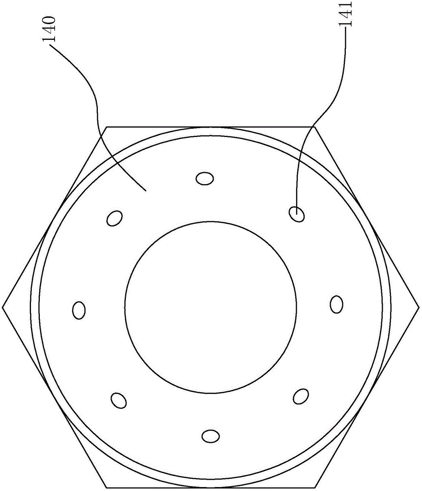
[0050] like figure 1 , figure 2 As shown, the intake assembly includes an intake pipe 130 , an intake nozzle 140 and a sp...


PUM


Abstract

The invention provides a fuel gas burner and belongs to the technical field of burning equipment. According to the fuel gas burner, the technical problems that gas blending is not uniform, combustion is not sufficient and noise is large by means of an existing burner are solved. The fuel gas burner comprises a first gas blending pipe, a second gas blending pipe, a gas blending shell body, a burner cover body and burner ports. One end of the first gas blending pipe communicates with the exterior, and air and fuel gas can be aerated into the first gas blending pipe; the second gas blending pipe communicates with the first gas blending pipe and an included angle is formed between the first gas blending pipe and the second gas blending pipe; the interior of the gas blending shell body communicates with the second gas blending pipe; the burner cover body is arranged on the gas blending shell body in a covering manner; and the multiple burner ports are arranged and distributed on the burner cover body, the burner ports extend obliquely from the rim of the burner cover body to the off-centered side at the interior of the burner cover body, and the width of each burner port decreases gradually from the rim of the burner cover body to the interior of the burner cover body. The air and the fuel gas are more uniform after multiple blending, and the combustion efficiency is high; the shapes, sizes and positions of the burner ports are reasonably designed, and the noise when gas is discharged is reduced; the stability of the gas when the gas is discharged is improved, and the combustion of the gas is made to be more sufficient.

Description

technical field [0001] The invention belongs to the technical field of combustion devices and relates to a gas burner. Background technique [0002] A gas burner is defined as a device that converts substances into heat energy through the chemical reaction of combustion, that is, air and fuel are mixed in an appropriate proportion through a premixing device to fully burn the heat energy device. [0003] The gas mixing structure and the flame hole structure are two important structures that affect the use effect of the burner. The existing burner can basically meet the existing use requirements, but there are the following technical problems in the above two links: 1. The gas mixing process is relatively slow. Simple, generally one-time gas mixing, resulting in poor gas mixing effect, uneven mixing of gas and air, resulting in low combustion efficiency and serious environmental pollution; 2. The design of the fire hole is unreasonable, resulting in loud noise when the gas flo...

Claims


Application Information

Patent Timeline
Patent Type & Authority Patents(China)
IPC IPC(8): F23D14/02F23D14/64F23D14/58
CPCF23D14/02F23D14/58F23D14/64F23D2203/007
Inventor 严若男
Owner NINGHAI JINING KITCHEN UTENSILS CO LTD
Why Eureka
Try Eureka