A kind of inner hole thermal spraying device and method

A technology of thermal spraying and inner holes, applied in the direction of spraying devices, etc., can solve the problems of difficult to improve the comprehensive performance of parts, large operating space of the gun body, and small space utilization rate, so as to improve quality, flexible structural design, and small space utilization rate Effect

Active Publication Date: 2018-06-19
NANTONG GAOXIN ANTIWEAR MATERIALS TECH CO LTD
View PDF8 Cites 0 Cited by
  • Summary
  • Abstract
  • Description
  • Claims
  • Application Information

AI Technical Summary

Problems solved by technology

As we all know, there are many input pipes connected to the thermal spray gun, which leads to a large operating space for the entire gun body, making it difficult to spray or fail to spray the inner wall of the tube with a small diameter due to the problem of the angle and depth of the spray gun, which eventually leads to The comprehensive performance of parts is difficult to improve, which affects their service life
Therefore urgently need to develop a kind of inner hole thermal spraying device and method that space utilization rate is little, spraying is convenient and improves the service life of parts, after searching, do not find the same or similar technical scheme with the present invention

Method used


Image

  • A kind of inner hole thermal spraying device and method
  • A kind of inner hole thermal spraying device and method
  • A kind of inner hole thermal spraying device and method

Examples


Embodiment 1

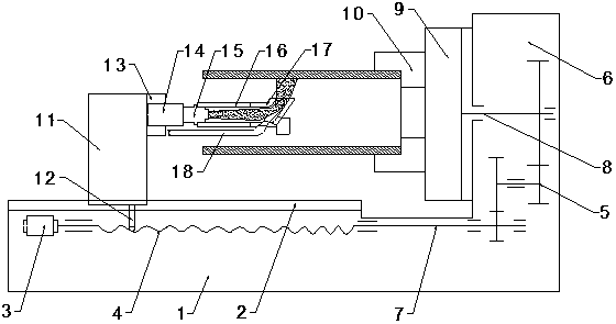
[0033] Such as figure 1 and figure 2 As shown, the present invention discloses a thermal spraying device for inner holes, which includes a worktable 1, a rotary clamping device and a feeding device arranged above the worktable 1 .

[0034] The upper end surface of the workbench 1 has a slide rail 2 along the long axis direction, and a motor 3 is installed on the inner side, and the end of the motor 3 is connected with a lead screw 4 arranged along the long axis direction of the workbench 1 .

[0035] The rotary clamping device is set on the side away from the motor 3 above the workbench 1, and mainly includes a box body 6, a rotating shaft 9 arranged at the end of the box body 6, and a collet A10; The gear set 5 at the end 8, the input end 7 is connected with the end of the lead screw 4 away from the motor 3, and the output end 8 is connected with the end of the rotating shaft 9.

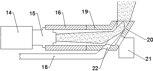
[0036] The feeding device comprises a spray gun support 11, a spray gun body 14 arranged at t...

Embodiment 2

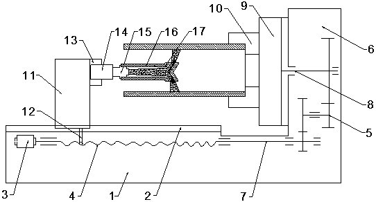
[0044] Such as image 3 , Figure 4 and Figure 5 As shown, the present invention discloses a thermal spraying device for inner holes, which includes a worktable 1, a rotary clamping device and a feeding device arranged above the worktable 1 .

[0045] The upper end surface of the workbench 1 has a slide rail 2 along the long axis direction, and a motor 3 is installed on the inner side, and the end of the motor 3 is connected with a lead screw 4 arranged along the long axis direction of the workbench 1 .

[0046] The rotary clamping device is set on the side away from the motor 3 above the workbench 1, and mainly includes a box body 6, a rotating shaft 9 arranged at the end of the box body 6, and a collet A10; The gear set 5 at the end 8, the input end 7 is connected with the end of the lead screw 4 away from the motor 3, and the output end 8 is connected with the end of the rotating shaft 9.

[0047] The feeding device comprises a spray gun support 11, a spray gun body 14 ar...


PUM


Abstract

The invention relates to an inner hole thermal spraying device and method. Firstly, the sand blasting derusting and roughening treatment are performed on the inner wall of a pipe fitting; then, the pipe fitting is fixed within a chuck A, and a motor is started to enable a lead screw, a gear set and a rotating shaft to synchronously work, so that a spray gun bracket moves towards one side of a rotary clamping device in the central axis direction of the pipe fitting; when a port of an inclined section of a front end terminal is aligned with one end, far from the chuck A, of the pipe fitting, a paint nozzle is started, and when the front end terminal moves to one end of the chuck A, the spraying of a first layer is finished; and finally, priming coat spraying is performed on the inner wall of the pipe fitting by the same method and the inner hole thermal spraying device. The inner hole thermal spraying device and the method have the following advantages: the paint nozzle of the inner hole thermal spraying device is low in space utilization rate, and the inner hole thermal spraying device can spray the inner wall of a pipe fitting with a relatively small caliber, and is reasonable in structural design; and the device adopts mechanical connection at joints, so that free disassembly is achieved, and the device is simple in structure and low in cost, and solves the problems of the inner hole surface spraying of an existing thermal spraying technology.

Description

technical field [0001] The invention relates to the field of surface engineering, in particular to an inner hole thermal spraying device and method. Background technique [0002] Thermal spraying technology is a method of spraying molten spraying materials on the surface of parts through high-speed airflow to form sprayed coatings to prepare metal-based ceramic coatings. It appeared in the early 20th century, and Dr. M.U.Schoop of Switzerland first completed its spraying device in 1910. This technology has a wide range of spraying substrates and spraying materials, and is not limited; the spraying object can be complex parts, not limited by the shape of the parts; the operation is simple and convenient, and it can have a good effect on the wear resistance, hardness and thermal conductivity of the substrate. Improve the effect, and will not cause large stress deformation of the matrix and other advantages. Therefore, it plays an important role in the field of surface engine...

Claims


Application Information

Patent Timeline
Patent Type & Authority Patents(China)
IPC IPC(8): B05B13/06
CPCB05B13/0645
Inventor 倪红军魏金栋朱昱孙书刚张宇汪兴兴吕帅帅黄明宇李小武
Owner NANTONG GAOXIN ANTIWEAR MATERIALS TECH CO LTD
Why Eureka
Try Eureka