Forging piston four-station drilling clamp and machining method

A drilling jig and four-station technology, which is applied in the direction of manufacturing tools, metal processing equipment, metal processing machinery parts, etc., can solve the problems of low production efficiency and difficulty in batch production, and achieve high processing efficiency, high space utilization rate, The effect of improving processing efficiency

Active Publication Date: 2019-11-01
ANHUI ANHUANG MACHINERY
View PDF8 Cites 4 Cited by
  • Summary
  • Abstract
  • Description
  • Claims
  • Application Information

AI Technical Summary

Problems solved by technology

The disadvantage is that one machine tool must be equipped with one worker, and only one product can be processed at a time. The production efficiency is low, and the production line occupies an area, which brings difficulties to mass production. It is urgent to design a conventional forged steel with fast processing and high efficiency. Rough drilling jig and processing method for piston drilling

Method used


Image

  • Forging piston four-station drilling clamp and machining method
  • Forging piston four-station drilling clamp and machining method

Examples


Embodiment 1

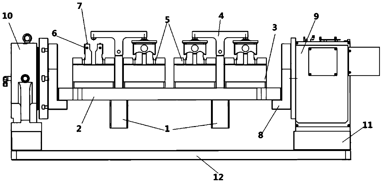
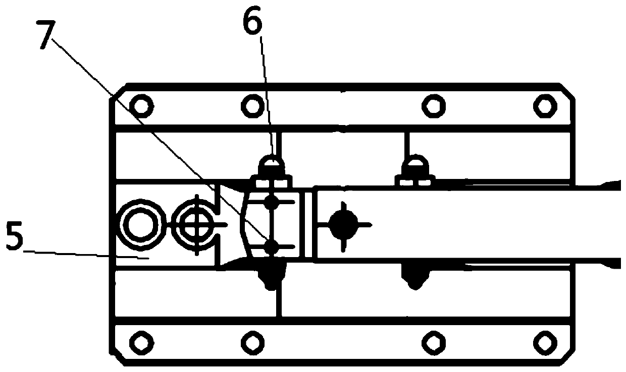
[0027] see Figure 1-2 , a forging piston four-station drilling fixture, including a rotary table and a backing plate 2, four precision centering vises 3 are fixedly arranged on the upper surface of the backing plate 2, and four precision centering vises 3 are fixed on the backing plate The upper surface of 2 is arranged in a line and aligned in the X direction. The center distances of the left one and left three precision centering vises 3, the left two and left four precision centering vises 3 are all consistent with the center distances of the double spindles of the machining center. The two ends of the upper surface of each precision centering vise 3 are symmetrically fixed with two claws 5, and the upper part of the claws 5 is equipped with an elastic plunger 6 that protrudes on both sides to tighten the workpiece, and the elastic plunger 6 is set. It is convenient to fix the workpiece, making the fixation convenient and quick. The top of the claw 5 is welded and fixed ...

Embodiment 2

[0030] On the basis of Embodiment 1, the index plate 9 and the tailstock 10 are respectively fixed on the base base 12 through the riser block 11 , thereby maintaining the integrity of the whole device.

[0031] Working principle and processing method of the present invention:

[0032] Assembly: Assemble the special fixtures and tools of the type required for this processing, and calibrate the accuracy of the clamping position, and the double-spindle machine tool is ready to start;

[0033] Feeding: Put the four piston workpieces into the jaws 5 of the special fixture in turn by manual or mechanical hands, and the elastic plunger 6 on the upper part of the jaws 5 is automatically tightened, and the jaws 5 and elastic plunger 6 are waiting for the inside of the hole to be drilled. Peripheral positioning, the support column 7 on the top of the jaw 5 is positioned on the inner top surface of the workpiece;

[0034] Clamping: After the workpiece is placed, the two oil cylinders 1...


PUM


Abstract

The invention relates to the field of forging piston machining and particularly discloses a forging piston four-station drilling clamp and a machining method. The forging piston four-station drillingclamp comprises a rotating worktable and a cushion plate, four precise centering vices are fixedly arranged on the upper surface of the cushion plate, and two clamping claws are symmetrically fixedlyarranged at the two ends of the upper surface of each precise centering vice. Two supporting pillars are welded and fixed to the top of each clamping claw. The heights of the supporting pillars must be kept consistent with the rotating center distance of the rotating worktable. An oil cylinder is arranged between each pair of precise centering vices, wherein a T-shaped pressing plate is assembledand fixed to the top end portion of a rod in the oil cylinder, and the two ends of the T-shaped pressing plates are located above the corresponding clamping claws. The cushion plate is fixed in the rotating worktable through two clamping plates. Thus, 180-degree overturning machining can be achieved, and work is completed through feeding, clamping, machining and discharging. The forging piston four-station drilling clamp and the machining method have the beneficial effects that the structure is simple, operation is convenient, the machining efficiency is high, the production cost is low, the space utilization rate is high, and popularization and implementation are facilitated.

Description

technical field [0001] The invention relates to the field of forging piston processing, in particular to a forging piston four-station drilling jig and a processing method. Background technique [0002] Compared with traditional aluminum alloy pistons, forged steel pistons have higher strength (≥850Mpa) and are suitable for high compression ratio engines. Therefore, the rigidity of the machine tool and the precision of the fixture are required for rough machining of the forged steel piston. [0003] The rough drilling method of the conventional forged steel piston is as follows: use a horizontal drilling machine, manual loading and unloading single-station clamping, and simultaneous drilling with double cutters facing in the X direction. It takes about 40 seconds for one machine tool to process one product, and the single-shift production capacity is about 675 pieces. The disadvantage is that one machine tool must be equipped with one worker, and only one product can be pr...

Claims


Application Information

Patent Timeline
Patent Type & Authority Applications(China)
IPC IPC(8): B23Q3/08
CPCB23Q3/061B23Q3/062B23Q3/082
Inventor 黎昺哲李少峰徐凝慧
Owner ANHUI ANHUANG MACHINERY
Why Eureka
Try Eureka