Cleaning line for crankcases

A technology for cleaning lines and crankcases, applied in the fields of crankcase processing parts and crankcase cleaning lines, can solve the problems of inconvenient use, difficult cleaning of deep stains, poor cleaning effect, etc., and achieve the effect of high purification efficiency

Inactive Publication Date: 2016-08-10
嘉兴市立丰机械制造有限公司
View PDF7 Cites 2 Cited by
  • Summary
  • Abstract
  • Description
  • Claims
  • Application Information

AI Technical Summary

Problems solved by technology

[0002] The part of the lower part of the cylinder block used to install the crankshaft is called the crankcase. After the crankcase is processed, there will be a lot of burrs and oil. To make the workpiece can be used as soon as possible, a series of degreasing, spraying and water blowing are required. The system, these systems are used alone on the current equipment, that is to say, at least two or even more equipment are required to work to make the workpiece effective, which will not only take up a lot of time space, and the required purchase cost is relatively expensive, maintenance is also very troublesome, and it is inconvenient to use; Chinese patent application number: 201420061912.5 discloses a crankcase cleaning machine, including a body, an electric control box connected to the body, The water inlet valve and overflow valve on the body, the main drive shaft and the driven shaft on the body, the delivery fixture system connected between the main drive shaft and the driven shaft, and the emergency stop switch connected to the body , the body is equipped with a degreasing spray system, a cleaning spray system and a compressed air blowing system, the design is reasonable, the structure is firm, the work is reliable, the work efficiency is high, the operation is convenient, the safety hazard is reduced, and the use is safe; but its cleaning effect Poor, difficult to clean on some deep stains

Method used


Image

  • Cleaning line for crankcases
  • Cleaning line for crankcases

Examples


Embodiment Construction

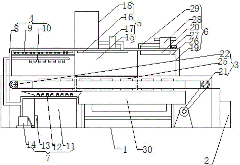
[0015] Such as figure 1 with figure 2 The shown crankcase cleaning line includes a base body 1, an electric control box 2 for total circuit control is installed on the side of the base body 1; a crankshaft transmission mechanism 3 is installed on the base body 1; The crankshaft is sent to the seat body 1 in turn, and the seat body 1 is sequentially provided with a degreasing spray cleaning mechanism 4, a flushing mechanism 5 and a drying mechanism 6 above the crankshaft transmission mechanism 3; A lower degreasing spray mechanism 7 is arranged below the mechanism 3;

[0016] The degreasing spray mechanism 4 includes a first cavity 8; an ultrasonic cleaning probe 9 and an upper degreasing spray pipe 10 are installed inside the first cavity 8; the lower degreasing spray mechanism 7 includes a lower cavity 11; A lower degreasing spray pipe 12 is installed inside the lower cavity 11; the bottom of the lower cavity 11 is connected to the first pump body 14 through a filter 13; t...


PUM


Abstract

The invention discloses a cleaning line for crankcases. The cleaning line comprises a base body; an electric cabinet for general control over circuits is installed on the side edge of the base body; the base body is provided with a crank conveying mechanism; the base body is sequentially provided with a degreasing spraying and cleaning mechanism, a washing mechanism and a drying mechanism above the crank conveying mechanism; the base body is provided with a lower degreasing spraying mechanism below the crank conveying mechanism; the degreasing spraying and cleaning mechanism comprises a first cavity, and an ultrasonic cleaning probe and an upper degreasing spraying pipe are installed on the inner side of the first cavity. According to the cleaning line for the crankcases, degreasing cleaning and ultrasonic cleaning are adopted, and therefore stains can be separated from the surfaces of cranks; the stains are directly removed through washing by clean water, clean gas is directly adopted for hot drying after cleaning, and therefore the cleaning line can be cleaned, and the purification efficiency of the cranks is high through automatic control.

Description

technical field [0001] The invention relates to a crankcase processing part, in particular to a crankcase cleaning line, which belongs to the technical field of crankcase processing equipment. Background technique [0002] The part of the lower part of the cylinder block used to install the crankshaft is called the crankcase. After the crankcase is processed, there will be a lot of burrs and oil. To make the workpiece can be used as soon as possible, a series of degreasing, spraying and water blowing are required. The system, these systems are used alone on the current equipment, that is to say, at least two or even more equipment are required to work to make the workpiece effective, which will not only take up a lot of time space, and the required purchase cost is relatively expensive, maintenance is also very troublesome, and it is inconvenient to use; Chinese patent application number: 201420061912.5 discloses a crankcase cleaning machine, including a body, an electric co...

Claims


Application Information

Patent Timeline
Patent Type & Authority Applications(China)
IPC IPC(8): B08B3/02B08B3/08B08B3/12F26B15/04
CPCB08B3/022B08B3/08B08B3/123F26B21/00
Inventor 关晓杰蒋宁
Owner 嘉兴市立丰机械制造有限公司
Why Eureka
Try Eureka