Method for forging workblank of transmission disc of locomotive

A technology of drive discs and blanks, applied in the directions of wheels, vehicle parts, transportation and packaging, etc., can solve problems such as low production efficiency, reduced service life of machine drive discs, and increased man-hours and costs.

Active Publication Date: 2016-08-10
CRRC QISHUYAN INSTITUTE CO LTD
View PDF8 Cites 10 Cited by
  • Summary
  • Abstract
  • Description
  • Claims
  • Application Information

AI Technical Summary

Problems solved by technology

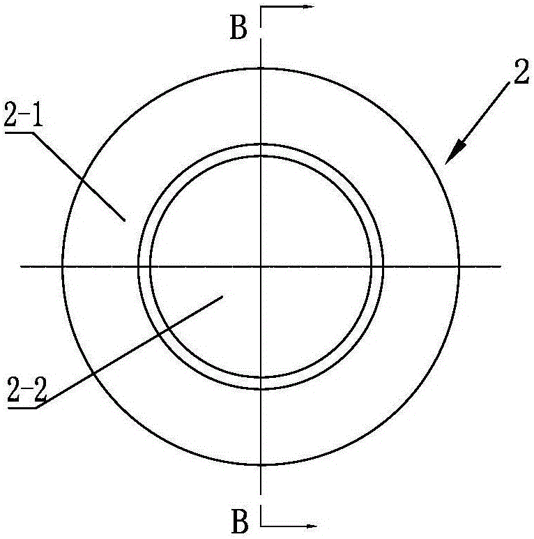
When free forging is used to make blanks, see image 3 , 4 As shown, the blank is forged to form a thick ring-shaped cake 2-1. The ring-shaped cake 2-1 has a blank 2 with a central boss 2-2. The raw material consumption of this blank is as high as 7 to 10 times that of the parts. Blank heating energy is seriously wasted, production efficiency is low, and blank manufacturing costs are high
Furthermore, because the blank is relatively thick, it will increase a lot of subsequent heat treatment, machining hours and costs, and the production efficiency is low.
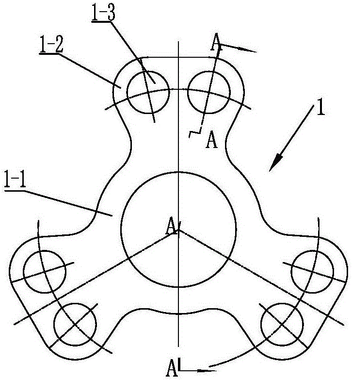
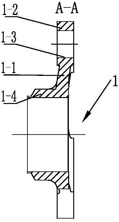
Using the free forging method to manufacture the blank, the material streamline will be cut off during machining, especially the material streamline used to connect the ears of the traction wheel pair will be cut transversely, which greatly reduces the comprehensive mechanical properties of the product, and reduces the machine transmission disc. service life

Method used


Image

  • Method for forging workblank of transmission disc of locomotive
  • Method for forging workblank of transmission disc of locomotive
  • Method for forging workblank of transmission disc of locomotive

Examples


Embodiment Construction

[0039] See Figure 5 Shown, the method for forging locomotive transmission plate blank of the present invention, carries out according to the following steps.

[0040] ⑴, blanking.

[0041] Select the raw material of the required material, such as carbon steel or alloy steel, and cut the blank 3 according to the weight. Figure 6 The blank 3 shown can greatly improve the utilization rate of raw materials.

[0042] ⑵, heating.

[0043] Put the billet 3 into the heating furnace and heat it to 1100°C-1180°C to reduce the yield stress of the billet after heating. Forging and final forging are formed, and the three ear parts 7-1 of the forging blank can be formed full, so that the dimensions of the forging blank can be stabilized within the tolerance range.

[0044] ⑶ Pre-forging.

[0045] The pre-forging of the present invention adopts the combination of open forging die and free forging. See Figure 7-11 As shown, the heated blank 3 is put into the lower cavity of the pre-...


PUM


Abstract

The invention relates to a method for forging a workblank of a transmission disc of a locomotive. A selected raw material is cut into a blank according to weight; the blank is placed into a heating furnace to be heated to 1100 DEG C to 1180 DEG C; the heated blank is placed into a lower mold cavity of a pre-forging lower die to be positioned, the blank is forged to enable a material of the blank to flow in a pre-forging mold cavity of a pre-forging upper die and the pre-forging mold cavity of the pre-forging lower die in the free upsetting radial direction, and a molded pre-forging piece forms a corresponding thinning part at a protrusion bridge part and correspondingly forms a thickening part at the position of a cavity; the pre-forging piece is turned over to be placed into the mold cavity of the pre-forging lower die to be automatically positioned, the pre-forging piece is forged to enable the material of the pre-forging piece to flow in finish-forging mold cavities of a finish-forging upper die and a finish-forging lower die in the radial direction, and a molded finish-forging piece outwards extends along a disc body to form three uniformly-distributed lug parts and a shaft sleeve located at the middle portion of the disc body; and parting-line flashes of the finish-forging piece are cut off, connecting skin is punched away, and the workblank of the forging piece is prepared. By means of the method, the manufacturing cost is reduced, the production efficiency is improved, the complete streamline of a material of the transmission disc product of the locomotive can be kept, and the transmission disc of the locomotive has the excellent overall performance.

Description

technical field [0001] The invention relates to a method for forging a locomotive transmission disc blank, belonging to the technical field of locomotive transmission disc manufacture. Background technique [0002] The traction motor of the locomotive transmits the motion to the hollow shaft through the traction gear pair mechanism, and the hollow shaft and the transmission disc of the locomotive are connected with the transmission disc through welding or couplings, and the transmission disc is connected with six connecting rods through transmission pins, and the connecting rods output the motion Give the locomotive wheels. As a key part of the transmission part of the locomotive, the locomotive transmission disc not only bears the huge torque transmitted by the hollow shaft, but also bears the reactionary circular cyclic stress of the six connecting rods, and also bears the vibration and axial cyclic stress transmitted by the wheelset during operation. It is extremely hars...

Claims


Application Information

Patent Timeline
Patent Type & Authority Applications(China)
IPC IPC(8): B21K1/32B21J5/02B21J1/06
CPCB21J1/06B21J5/02B21J5/022B21K1/32
Inventor 阮发林张建鑫侯磊杨诚
Owner CRRC QISHUYAN INSTITUTE CO LTD
Why Eureka
Try Eureka