Device for machining metal mirror by laser ablation

A technology of laser ablation and metal, which is applied in the field of mold manufacturing, can solve problems such as difficult to ensure dimensional accuracy, pollute the environment, and low processing efficiency, and achieve the effect of free control of roughness, no pollution, and high processing accuracy

Inactive Publication Date: 2016-08-10
SUZHOU NEW GALAXY LASER TECH
View PDF9 Cites 5 Cited by
  • Summary
  • Abstract
  • Description
  • Claims
  • Application Information

AI Technical Summary

Problems solved by technology

However, manual grinding and polishing are subject to some limitations, such as the need for skilled skills and experience, but it is also difficult to ensure the consistency and reproducibility of the mirror surface, and it is also difficult to ensure the accuracy of dimensions by manual grinding and polishing, and this process is very time-consuming
The other is to use machine grinding for processing. The workpiece is placed on a continuously rotating disc. The disc is covered with metallographic polishing cloth, and the workpiece also rotates with the disc. At the same time, corrosive polishing liquid or diamond is sprayed. Paste, repeated friction between the workpiece and the cloth on the disc can also achieve the mirror effect, but the disadvantage is that it cannot process special-shaped parts, because the trajectory is inconsistent during rotation, resulting in poor flatness after processing, low processing efficiency, and the polishing liquid is corrosive ,polluted environment

Method used


Image

  • Device for machining metal mirror by laser ablation
  • Device for machining metal mirror by laser ablation

Examples


Embodiment Construction

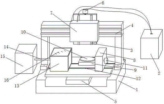
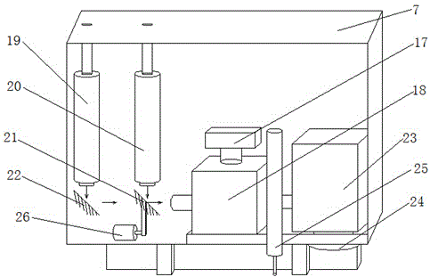
[0017] Attached below figure 1 with 2 The present invention is further described. figure 1 with figure 2 Schematically shows a device of the present invention that uses laser ablation to process metal mirrors, such as figure 1 As shown, it includes an operation platform 1 and a laser 2. The operation platform 1 is provided with a five-axis linkage structure of Z-axis 3, X-axis 4, Y-axis 5, A-axis and C-axis. The Z-axis 3 is provided with The Z-axis motor 6 and the cavity 7, the Z-axis 3, the Z-axis motor 6 and the cavity 7 are all arranged on the X-axis 4, as figure 2 As shown, the cavity 7 is provided with a camera 17, an automatic focusing device 18, a high-power laser output head 19, a low-power laser output head 20, an optical path switching mirror 21 and a total reflection mirror 22. Next to the camera 17 A scanning vibrating mirror 23 is also connected, and a flat-field lens 24 is arranged below the scanning vibrating mirror 23 . The Y-axis 5 is provided with an A...


PUM


Abstract

The invention discloses a fully automatic, high-efficiency and high-quality equipment for processing metal mirrors by laser ablation, which includes an operation platform and a laser, and the operation platform is equipped with Z-axis, X-axis, Y-axis, A-axis and C-axis The five-axis linkage structure of the axis, the Z-axis is equipped with a Z-axis motor and a cavity, the Z-axis, the Z-axis motor and the cavity are all set on the X-axis, and the cavity is equipped with a camera and an automatic focus device, a high-power laser output head, a low-power laser output head, an optical path switching mirror and a total reflection mirror, the camera is also connected to a scanning galvanometer, and a flat-field lens is arranged below the scanning galvanometer. The Y-axis is provided with an A-axis and a C-axis vertically, the A-axis is provided with a swing structure and an A-axis motor, the A-axis motor is provided with a processing table, and the C-axis is provided with a C-axis motor. The mirror surface processing has good consistency, and the roughness can be controlled freely, and it ensures no pollution, highlighting the advantages of environmental protection.

Description

technical field [0001] The invention belongs to the field of mold manufacturing, in particular to a device for processing the surface of a mold by laser. Background technique [0002] Some molds used in metal, glass, plastic and other manufacturing industries require high-quality surface finish and roughness, which directly affects product quality, wear resistance, optical properties and visual effects. The pre-processing of the mold is processed by lathes, grinders, milling machines, wire cutting, electric sparks and other equipment. The surface roughness is relatively large. To obtain a high degree of finish, there are currently two traditional methods for surface improvement. One is to use fine emery wheels. After grinding, use manual grinding and polishing, and use special cloth with light corrosive liquid or diamond paste to repeatedly rub against the surface of the mold to form a mirror effect. However, manual grinding and polishing are subject to some limitations, su...

Claims


Application Information

Patent Timeline
Patent Type & Authority Applications(China)
IPC IPC(8): B23K26/34B23K26/08B23K26/14B23K26/70
Inventor 肖阳春任建华
Owner SUZHOU NEW GALAXY LASER TECH
Why Eureka
Try Eureka