Electro-hydraulic hybrid power drive system

An electro-hydraulic hybrid and power-driven technology, applied in hybrid vehicles, power units, pneumatic power units, etc., can solve the problems of inability to meet the requirements of working conditions, insufficient starting and climbing ability, and unstable engine stability. The effect of high oil rate, diversified working modes, and market competitive advantage

Active Publication Date: 2016-08-10
SUZHOU KAIBO YIKONG DRIVE TECH CO LTD
View PDF6 Cites 18 Cited by
  • Summary
  • Abstract
  • Description
  • Claims
  • Application Information

AI Technical Summary

Problems solved by technology

[0004] (1) In the actual working conditions of the vehicle, the engine cannot be stabilized at a certain high-efficiency operating point during the working process, which will cause an increase in fuel consumption;
[0005] (2) AMT gearbox hybrid system and ISG hybrid system cannot meet the requirements of ultra-low-speed vehicles for working conditions, such as snowplows, sprinklers, etc.;
[0006] (3) When the vehicle speed is lower than 20km / h, the vehicle is driven by the motor, and the engine only intervenes when the vehicle reaches a certain speed, resulting in insufficient starting and climbing ability

Method used


Image

  • Electro-hydraulic hybrid power drive system
  • Electro-hydraulic hybrid power drive system
  • Electro-hydraulic hybrid power drive system

Examples


Embodiment 1

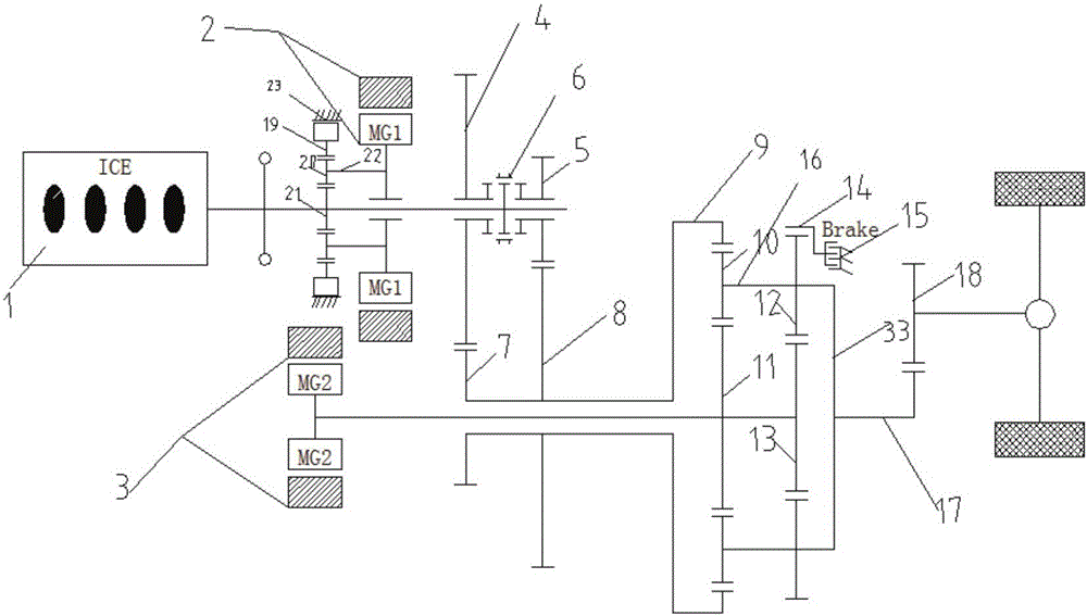
[0047] like figure 1 As shown, the shaft directly connected between the first motor 2 and the engine 1 is connected to a planetary row, and the planetary row includes a third ring gear 19, a third planetary gear 20, a third sun gear 21, and a third planet carrier 22. The engine 1 is coaxially connected to the third sun gear 21, the first motor 2 is sleeved on the shaft connected to the engine 1, and the first motor 2 is connected to the third planetary gear 20 through the third planet carrier 22. The third planetary gear 20 is meshed with the third sun gear 21 and the third ring gear 19 . The outer ring of the third ring gear 19 is provided with a second brake 23 , and the second brake 23 controls the movement state of the third ring gear 19 through separation or combination.

[0048] The shaft directly connected between the second motor 3 and the sun gear is a direct shaft connection, that is, the second motor 3 is coaxially connected with the first sun gear 11 and the secon...

Embodiment 2

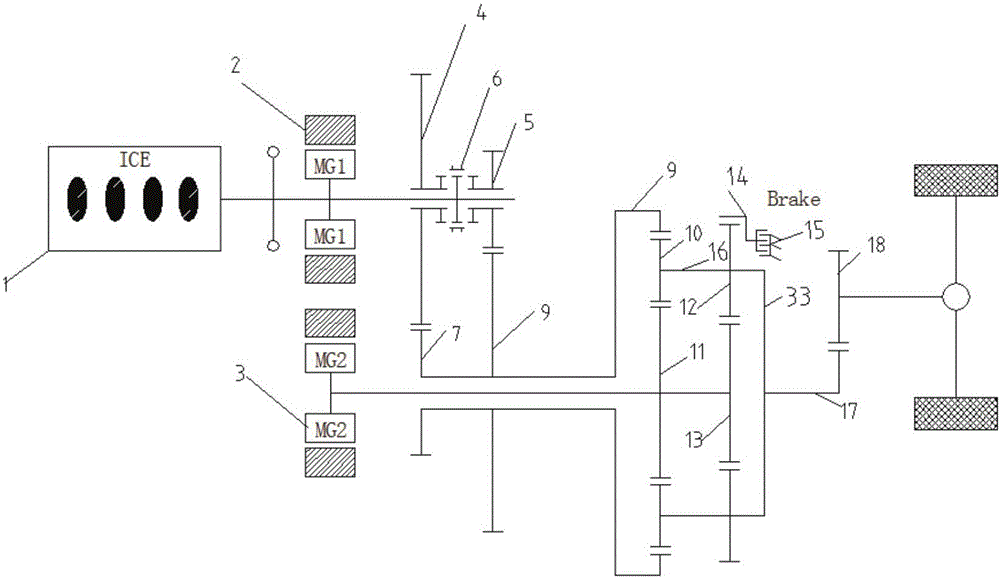
[0057] like figure 2 As shown, the shaft directly connected between the first motor 2 and the engine 1 is a direct shaft connection, that is, the first motor 2 and the engine 1 are coaxially connected. By connecting in this way, a quick start of the engine 1 can be realized. While the engine 1 is working, the first motor 2 is driven to generate electricity, and the first motor 2 outputs power to the second motor 3 to ensure that the second motor 3 has sufficient power to work, increase the coupling power, and reduce the working time of the engine fuel consumption.

[0058] The shaft directly connected between the second motor 3 and the sun gear is a direct shaft connection, that is, the second motor 3 is coaxially connected with the sun gear, and the second motor 3 is on the same shaft as the first sun gear 11 and the second sun gear 13 . Connected in this way, the forward speed of the car can be controlled directly by controlling the rotating speed of the second motor 3. W...

Embodiment 3

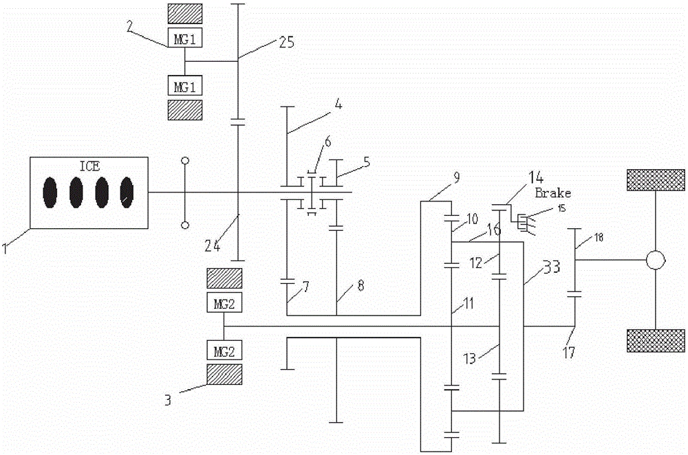
[0066] like image 3 As shown, the shaft directly connected between the first motor 2 and the engine 1 is geared, that is, the first motor 2 is fixedly connected with the eighth gear 25, the engine 1 is coaxially connected with the seventh gear 24, and the seventh gear 24 is connected with the eighth gear 25. The gears 25 are meshed. The engine 1, the seventh gear 24, the first gear 4, the second gear 5, and the double wet clutch 6 are on the same shaft. The first motor 2 is connected to the shaft connected to the engine by using gears, and by using gears of different sizes, relying on the speed ratio to output, it can provide a certain deceleration effect, so that the engine 1 can match the transmission power provided by the second motor 3 Matching, increase transmission power. And when starting the engine 1, the engine 1 can be started quickly by a smaller rotating speed.

[0067] The shaft directly connected between the second motor 3 and the sun gear is a direct shaft c...


PUM


Abstract

An electro-hydraulic hybrid power drive system comprises an engine, a first motor, a second motor, a first planetary gear set, a second planetary gear set and a hydraulic control gear shifting set connected with the engine, wherein the first motor is coupled with the engine; the second motor is coupled with the first planetary gear set and the second planetary gear set; the first planetary gear set and the second planetary gear set are coaxially connected; the hydraulic control gear shifting set comprises a first gear and a second gear; a wet type dual clutch unit is arranged between the first gear and the second gear; the first gear, the second gear and the wet type dual clutch unit are coaxially connected with the engine. With the adoption of the special electro-hydraulic hybrid power drive system, different work modes can be realized according to different requirements, ultra-low-speed stable operation can be realized, large torque is provided, fuel consumption is reduced, and the work requirement of a vehicle is met.

Description

technical field [0001] The invention relates to the technical field of new energy vehicle drive, in particular to an electro-hydraulic hybrid drive system. Background technique [0002] With the increasing proficiency of new energy technology, the drive system has achieved technological breakthroughs. At present, mainstream new energy vehicles adopt parallel and hybrid hybrid systems. Through the analysis and allocation of engine and motor characteristics and efficiency ranges, energy is efficiently utilized and recovered, thereby improving the efficiency of the entire system. [0003] In the existing technology, with the continuous advancement of science and technology, the promotion of new energy technology in the field of public facilities is becoming more and more extensive. It is currently used in public vehicles, such as snowplows, etc., and AMT gearbox hybrid systems, ISG hybrid systems are generally used Power system, AMT gearbox hybrid system, ISG hybrid system, al...

Claims


Application Information

Patent Timeline
Patent Type & Authority Applications(China)
IPC IPC(8): B60K6/365B60K6/445
CPCB60K6/365B60K6/445B60K6/36B60K6/387B60K6/442B60K6/547B60K2006/381Y02T10/62B60Y2200/92B60Y2400/73
Inventor 郝庆军
Owner SUZHOU KAIBO YIKONG DRIVE TECH CO LTD
Why Eureka
Try Eureka