Supercharge Your Innovation With Domain-Expert AI Agents!

Rotation angle detection device

A technology of rotation angle detection and detection unit, which is applied in the direction of measuring devices, using electric/magnetic devices to transmit sensing components, converting sensor outputs, etc., which can solve the problems of reduced detection accuracy and inability to completely eliminate offsets, etc.

Active Publication Date: 2020-05-19
DENSO CORP
View PDF10 Cites 0 Cited by
  • Summary
  • Abstract
  • Description
  • Claims
  • Application Information

AI Technical Summary

Problems solved by technology

In the above-mentioned Japanese Patent No. 5126325B2, the offset correction is performed inside the control unit, but unlike the case of using the output value from the full bridge circuit, there are phase differences caused by manufacturing errors, wiring resistance, temperature characteristics, etc. The offset cannot be completely eliminated without affecting the
In addition, when an abnormality occurs in part of the output signal, the calculation of the angle is continued using a sin-type signal or a cos-type signal output from one half-bridge, so there is a concern that the offset cannot be completely eliminated, and the detection accuracy may decrease compared with normal conditions.

Method used


Image

  • Rotation angle detection device
  • Rotation angle detection device
  • Rotation angle detection device

Examples


no. 1 approach

[0037] based on Figure 1 to Figure 10 A rotation angle detection device according to a first embodiment of the present invention will be described.

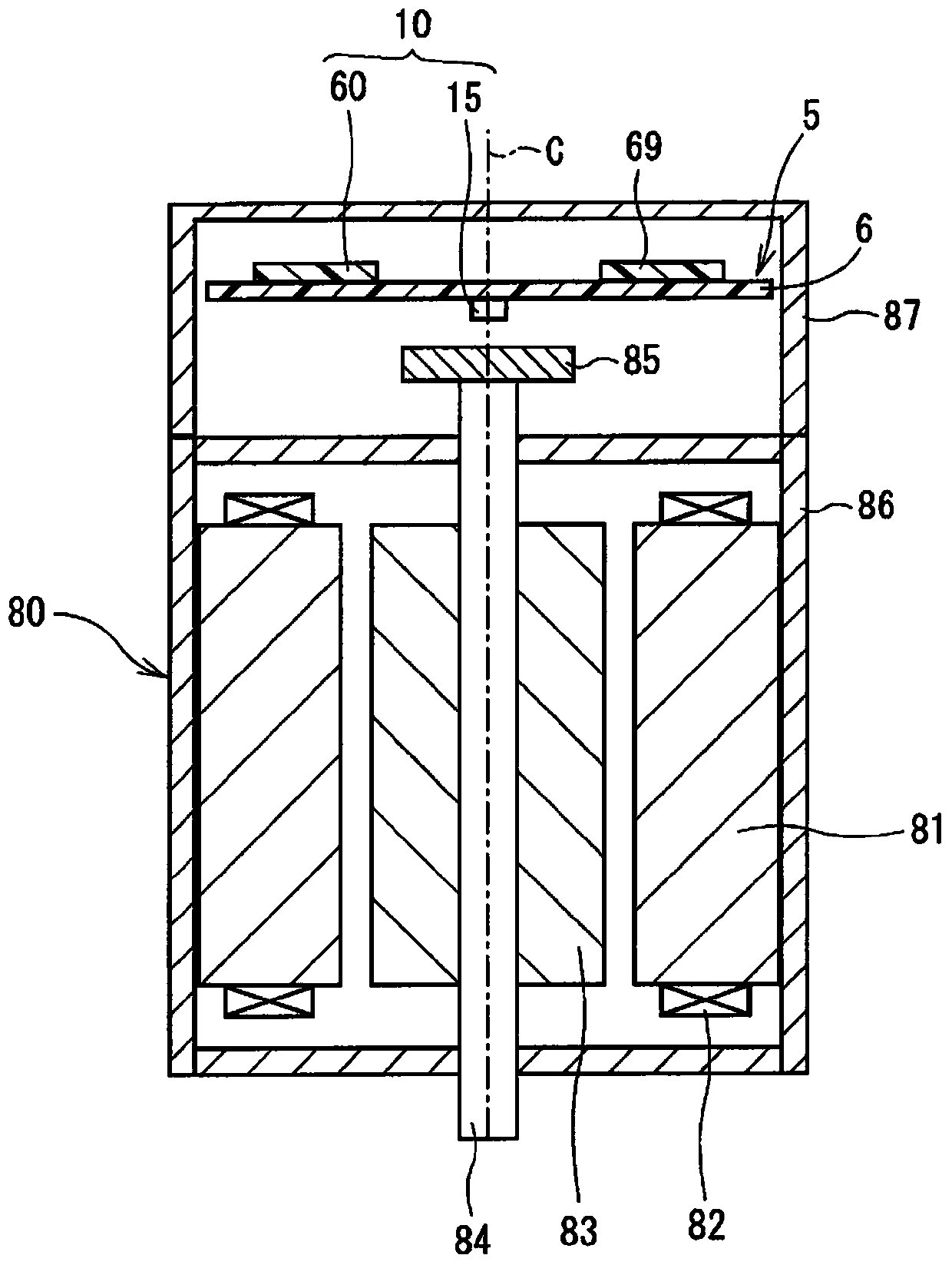
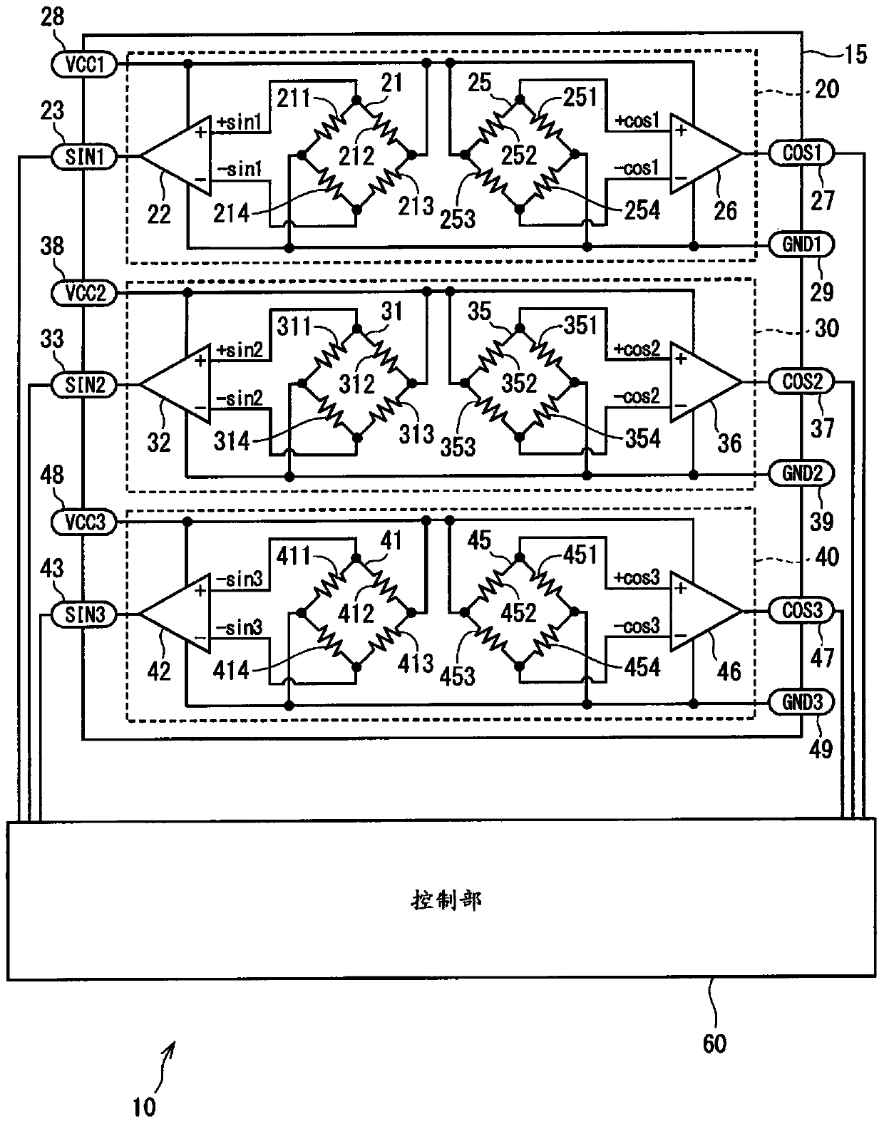
[0038] Such as Figure 1 ~ Figure 3 As shown, the rotation angle detection device 10 according to the first embodiment of the present invention has a sensor unit 15 and a control unit 60 and is used in the electric power steering device 1 for assisting steering operation of a vehicle.

[0039] figure 1 It is a diagram showing the overall configuration of a steering system 90 including the electric power steering apparatus 1 . The steering system 90 is composed of a steering wheel (steering wheel) 91 as a steering member, a steering shaft 92 , a pinion 96 , a rack shaft 97 , wheels 98 , and the electric power steering device 1 .

[0040] The steering wheel 91 is connected to a steering shaft 92 . A pinion 96 is provided at the front end of the steering shaft 92 , and the pinion 96 meshes with a rack shaft 97 . A pair of whee...

no. 2 approach

[0193] based on Figure 11 as well as Figure 12 A second embodiment of the present invention will be described.

[0194] based on Figure 11 The flowchart shown in the figure describes the angle calculation processing of this embodiment.

[0195] In S201 , the abnormality monitoring unit 65 judges whether or not the above-mentioned judgment expressions (1) to (4) are equal to or less than the judgment threshold value z. Here, four determination formulas are used, but one of the set of determination formulas (1) and (2) or the set of determination formulas (3) and (4) may be omitted. When it is determined that all of the determination expressions (1) to (4) are equal to or less than the determination threshold z (S201: Yes), the signal from the first sensor unit 20 is considered normal, and the process proceeds to S204. When it is judged that at least one of the judgment expressions (1) to (4) is greater than the judgment threshold z (S201: No), the process proceeds to S20...

no. 3 approach

[0214] based on Figure 13 A third embodiment of the present invention will be described.

[0215] based on Figure 13 The shown flowchart describes the angle calculation processing of this embodiment.

[0216]S301 and S302 with Figure 9 S101 and S102 in the same.

[0217] In S303 , the abnormality monitoring unit 65 determines whether the signals from the second sensor unit 30 and the third sensor unit 40 are normal. When it is determined that the signals from the second sensor unit 30 and the third sensor unit 40 are normal (S303: YES), the process proceeds to S304. When it is determined that the signal of the second sensor unit 30 or the third sensor unit 40 is abnormal (S303: NO), the process proceeds to S305.

[0218] When it is judged that the signals from all sensor parts 20, 30, 40 are normal (S301: Yes), or when it is judged that the signals from the second sensor part 30 and the third sensor part 40 are normal (S303: Yes) in S304, the angle calculation unit 62...


PUM


Abstract

A rotation angle detection apparatus includes three or more sensing portions and a controller. Each sensing portion includes a main circuit unit which is a full-bridge circuit and a subsidiary circuit unit which is a full-bridge circuit. An angle calculator of the controller calculates a rotation angle on the basis of a main signal corresponding to a main positive signal and a main negative signal outputted from at least one main circuit unit and a subsidiary signal corresponding to a subsidiary positive signal and a subsidiary negative signal outputted from at least one subsidiary circuit unit. An abnormality monitoring unit compares main signals and also compares subsidiary signals outputted from different sensing portions and monitors an abnormality occurrence according to a comparison result. A rotation angle can be thus detected with high accuracy.

Description

technical field [0001] The present invention relates to a rotation angle detection device. Background technique [0002] Conventionally, there is known a rotation angle detection device that detects a rotation angle by detecting a rotating magnetic field. For example, in Japanese Patent JP5126325B2, at least 4 output signals output from the midpoint of the half bridge are used to calculate the rotation angle. [0003] The output value from the half bridge circuit includes the offset deviation. In the above-mentioned Japanese Patent No. 5126325B2, the offset correction is performed inside the control unit, but unlike the case of using the output value from the full bridge circuit, there are phase differences caused by manufacturing errors, wiring resistance, temperature characteristics, etc. In the case of influence, the offset cannot be completely eliminated. In addition, when an abnormality occurs in part of the output signal, the angle calculation is continued using a s...

Claims


Application Information

Patent Timeline
Patent Type & Authority Patents(China)
IPC IPC(8): G01D5/12
CPCG01D5/12G01D5/24461G01D5/24485
Inventor 藤田敏博坂井利光
Owner DENSO CORP
Features
  • R&D
  • Intellectual Property
  • Life Sciences
  • Materials
  • Tech Scout
  • Unparalleled Data Quality
  • Higher Quality Content
  • 60% Fewer Hallucinations
Learn More