
High extinction ratio measurement method for optical fiber polarizer

A technology of polarizing device and measurement method, applied in the direction of testing optical performance, etc., can solve the problem that the measurement sensitivity performance is not improved, etc.

Active Publication Date: 2016-08-10
HARBIN ENG UNIV
View PDF9 Cites 17 Cited by
  • Summary
  • Abstract
  • Description
  • Claims
  • Application Information

AI Technical Summary

Problems solved by technology

The main problem to be solved is how to improve the accuracy and stability of polarization crosstalk measurement, and the measurement sensitivity performance has not improved

Method used


Image

  • High extinction ratio measurement method for optical fiber polarizer
  • High extinction ratio measurement method for optical fiber polarizer
  • High extinction ratio measurement method for optical fiber polarizer

Examples


Embodiment 1

[0109] Example 1: A high extinction ratio measurement method for an optical fiber polarization device

[0110] (1) Input the light beam from the input terminal y1 of the Y waveguide 113, and measure the crosstalk PER at point C c value.

[0111] (2) Input the light beam from the output terminal y2 of the Y waveguide 113, and measure the crosstalk PER at point D d value.

[0112] (3) The length of each section of polarization-maintaining optical fiber in the measurement component of quantitative crosstalk mark is selected, the polarization-maintaining optical fiber ps2 of 45 ° polarization analyzer 116, polarization-maintaining optical fiber 115, Y waveguide 113 output tail fiber y2, Y waveguide input tail Fiber y1, polarization-maintaining fiber 114, and polarization-maintaining fiber ps1 of 45° polarizer 111 are respectively set as: l 1 =0.6m, l 2 =0.6m, l 3 =0.1m, l 4 = 0.2m, l 5 = 0.3m, l 5 = 0.6m.

[0113] (4) Align the output end y2 of the Y waveguide 113 with th...


PUM


Abstract

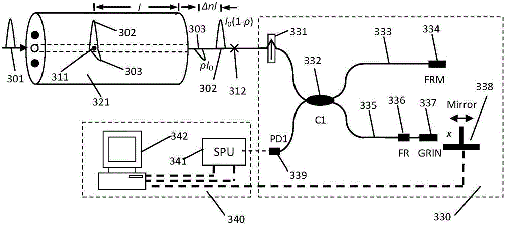
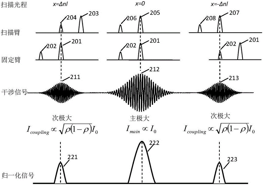
The invention belongs to the technical field of optical fiber measurement and relates to a high extinction ratio measurement method of an optical fiber polarizer. The high extinction ratio measurement method for an optical fiber polarizer comprises steps of respectively welding two segments of polarization maintaining optical fibers with various lengths on an input terminal and an output terminal of a Y waveguide (i.e. a high extinction ratio polarizing device to be detected) to construct a measurement assembly with a quantitative crosstalk mark; using a lumped extinction ratio tester to perform quantitative control on the extinction ratio of a welding point and recording the measurement value; setting the lengths of a polarizer pigtail, an analyzer pigtail, a high extinction ratio polarizer pigtail, and the welding polarization maintaining optical fiber; connecting the measurement assembly to the distributed optical fiber polarization crosstalk tester; and using a two-order crosstalk measurement value between the externally-connected optical fiber welding points to perform calibration and self-calibration on the extinction ratio of the polarizing device to be detected. During the measurement, the high extinction ratio measurement method of the invention can perform synchronous measurement on the crosstalk mark and the measurement peak, and avoids errors introduced by the change of the measurement environment and the member connection precision.

Description

technical field [0001] The design of the invention belongs to the technical field of optical fiber measurement, and in particular relates to a method for measuring high extinction ratio of an optical fiber polarization device. Background technique [0002] Polarization optical devices are an important part of high-precision optical measurement and sensing systems. At present, the performance testing and evaluation methods and devices of optical devices are backward, which seriously hinders the development of high-precision optical measurement and sensing systems. For example, the chip extinction ratio of lithium niobate integrated waveguide modulator (commonly known as Y waveguide), the core device of high-precision fiber optic gyroscope, has reached more than 80dB; The rate is around 50dB (according to the definition of energy, it is 10 5 ), the highest resolution is the Model 4810 polarization extinction ratio measuring instrument developed by the US dBm Optics company, a...

Claims


Application Information

Patent Timeline
IPC IPC(8): G01M11/02
CPCG01M11/02
Inventor 杨军梁帅苑勇贵吴冰彭峰李创喻张俊苑立波
Owner HARBIN ENG UNIV
Learn More