Grounding device shunt vector test method and device based on GPS second pulse

A technology of grounding device and test method, which is applied in the direction of measuring device, measuring electric variable, measuring current/voltage, etc., can solve problems such as limiting the effective distance of transmission, wireless signal coverage, affecting test results, etc., and achieves on-site testing. Convenience, strong anti-electromagnetic interference ability, and wide transmission distance

Active Publication Date: 2019-03-19
RED PHASE INC
View PDF5 Cites 0 Cited by
  • Summary
  • Abstract
  • Description
  • Claims
  • Application Information

AI Technical Summary

Problems solved by technology

Although this method can measure the shunt phase shift to a certain extent, because the wireless frequency selection communication technology and its equipment are easily affected by the field test environment, it will not only affect the transmission quality of the wireless signal in the strong electric field interference environment on site, Moreover, in the case of encountering on-site obstacles, the effective distance of its transmission is limited.
For example, for some very large substations or converter stations, there may be areas that cannot be covered by wireless signals
At the same time, this method requires a series of delays from wireless signal transmission to signal reception. Simple software algorithm correction will also introduce certain errors, which will affect the test results.
In addition, this method generally requires additional corresponding wireless transmission units and special frequency-selective communication equipment, which will also affect the workload of on-site testers to a certain extent.

Method used


Image

  • Grounding device shunt vector test method and device based on GPS second pulse
  • Grounding device shunt vector test method and device based on GPS second pulse
  • Grounding device shunt vector test method and device based on GPS second pulse

Examples


Embodiment Construction

[0031] Specific embodiments of the present invention will be described below with reference to the accompanying drawings.

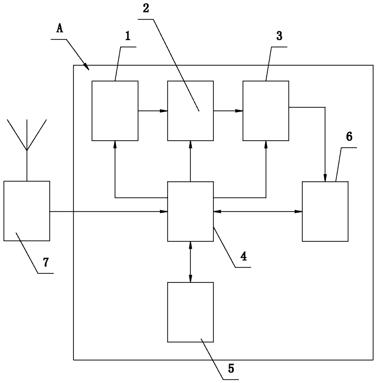
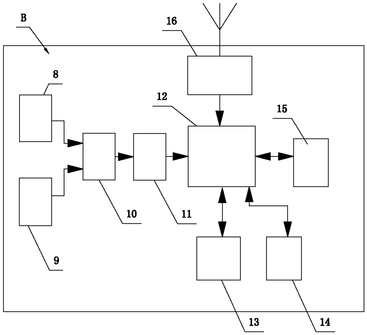
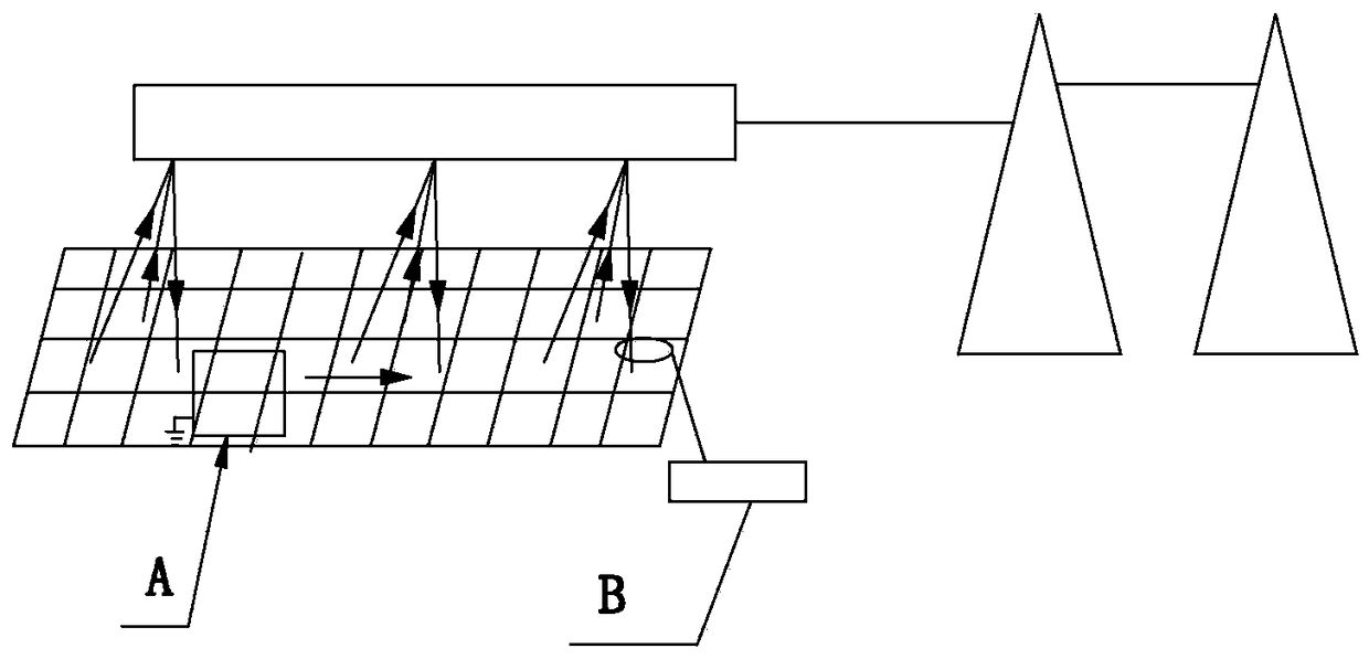
[0032] refer to figure 1 , figure 2 , image 3 and Figure 4 . The grounding device shunt vector test method based on the GPS second pulse designed by the present invention comprises the following steps:

[0033] (1) Arrange the current loop and voltage loop according to the measurement method of the characteristic parameters of the grounding device.

[0034] (2) The different-frequency signal output unit A injects a different-frequency current signal with a frequency of 40Hz~70Hz and a size of 0~20A into the current circuit of the arranged grounding device, and first connects the frequency-adjustable multimeter B of the measurement circuit to the different-frequency signal output device A is synchronized under the action of the PPS second pulse provided by the GPS artificial earth satellite, and then uses the flexible current coil configured by the a...


PUM


Abstract

The invention discloses a grounding device shunting vector testing method based on GPS pulse per second(PPS). The grounding device shunting vector testing method is characterized in that a PPS signal provided by a GPS artificial earth satellite is used to provide the same time marks for shunting vector measurement and signal output, and thereafter the phase difference between the measured shunting vector value and the signal output reference voltage value can be calculated synchronously, and therefore the shunting vector value can be calculated. The invention also discloses a grounding device shunting vector testing device. The extra reference voltage lead is not required, and the limitation and the obstruction of the on-site testing environment conditions such as the area of the to-be-tested grounding device and the existence of the barriers can be prevented, and in addition, the on-site electromagnetic interference capability is strong, and the shunting vector values of the inlet wires and the outlet wires can be accurately measured without dismounting various inlet wires and various outlet wires, and therefore the grounding impedance value of the grounding device can be acquired accurately, the transmission distance is long, the signal delay can be prevented, and the workload is small, and in addition, the on-site test and use can be simpler and more convenient.

Description

technical field [0001] The invention belongs to the field of grounding device state detection and evaluation, and relates to a grounding device shunt vector test method and its device, more specifically, a grounding device shunt vector test method and device based on GPS second pulse. Background technique [0002] Grounding impedance is an important index to evaluate the operation status of the grounding device, and it is of great significance for its accurate evaluation. However, since there are various incoming and outgoing lines in power plants and substations, the shunting effect of these incoming and outgoing lines will have a great impact on the grounding impedance test of the grounding device, resulting in the inability to accurately obtain the grounding impedance value of the grounding device during field testing, so it is very useful. It is necessary to accurately measure the shunt status of various incoming and outgoing lines on site in order to correct the groundi...

Claims


Application Information

Patent Timeline
Patent Type & Authority Patents(China)
IPC IPC(8): G01R19/00G01R27/02
CPCG01R19/00G01R27/02
Inventor 陈耀高林阳坡郭翔柯炳双
Owner RED PHASE INC
Why Eureka
Try Eureka