
Radar sub-array dividing optimization method based on difference algorithm

A differential algorithm and optimization method technology, applied in the field of radar, can solve the problem of reducing sub-array-level pattern sidelobes, etc., and achieve the effect of easy solution and implementation, and simple principle

Active Publication Date: 2016-08-10
XIDIAN UNIV
View PDF4 Cites 7 Cited by
  • Summary
  • Abstract
  • Description
  • Claims
  • Application Information

AI Technical Summary

Problems solved by technology

Hu Hang and others used the genetic evolution algorithm to divide the sub-array; Xiong Ziyuan et al. studied the optimal sub-array division method based on the clustering algorithm, and reviewed the sub-array division problem; Ge Pei et al. A simple non-uniform sub-array division method is proposed, which effectively reduces the side lobe of the sub-array level pattern; Wang Wenchang uses the particle swarm optimization algorithm to achieve the optimal non-uniform division of the linear array, and then extends the optimal division of the linear array to Planar array, so as to realize the formation of arbitrary directional beams in the desired area; the above method of subarray division has been applied in different application backgrounds, but the subarray division of large planar phased arrays is almost astronomical. , how to quickly search for a sub-array division method that satisfies the constraint performance is still a problem to be solved

Method used


Image

  • Radar sub-array dividing optimization method based on difference algorithm
  • Radar sub-array dividing optimization method based on difference algorithm
  • Radar sub-array dividing optimization method based on difference algorithm

Examples


Embodiment Construction

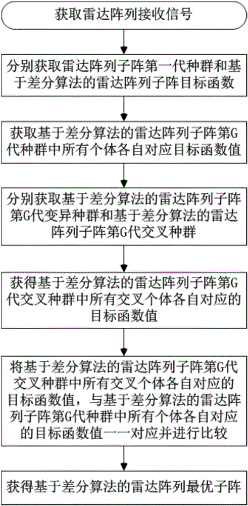
[0024] refer to figure 1 , is a flow chart of a radar sub-array division optimization method based on a differential algorithm of the present invention, and the radar sub-array division optimization method based on a differential algorithm comprises the following steps:

[0025] Step 1, get the radar array receiving signal D N×L , and according to the radar array received signal D N×L, the covariance matrix R of the radar array received signal and the steering vector S of the radar array received signal beam are calculated; where, N is the number of radar array elements, and L is the number of sampling units contained in the radar array received signal.

[0026] Specifically, first determine that the radar array is a uniform linear array, and obtain the received signal D of the radar array N×L ; The number of radar array elements is N, and the number of sampling units contained in the received signal of the radar array is L; then the radar array is placed at a distance of λ / ...


PUM


Abstract

The invention discloses a radar sub-array dividing optimization method based on a difference algorithm, comprising steps of obtaining a covariance matrix of a reception signal of the radar array and a beam pointing guiding vector, respectively arranging a radar array to divide the quantity of the sub-array, the number of the difference algorithm populations, and the variation operator, and a first generation variation rate, a crossover rate and a maximal evolution algebra in the difference algorithm, obtaining a target function and a Gth generation population XG of the sub-array of the radar array on the basis of the difference algorithm, calculating the Gth generation variation population of the sub-array of the radar array on the basis of the difference algorithm according to the first generation variation rate, obtaining the Gth generation crossover population of the sub-array of the radar array on the basis of the difference algorithm, performing comparison on the target function value corresponding to each of the crossover individuals and the target function value corresponding to each of the individuals in the XG in one-to-one correspondence to obtain the Gmth generation population X<Gm> of the sub-array of the radar array on the basis of the difference algorithm, and using the individual which has the biggest target function value in the X<Gm> as the optimal sub-array of the radar array based on the difference algorithm.

Description

technical field [0001] The invention belongs to the technical field of radar, and in particular relates to a radar sub-array division optimization method based on a differential algorithm, which is suitable for solving the problem of computational complexity and computational complexity of the adaptive algorithm caused by hundreds of array elements in large phased array radar The huge storage capacity and extremely poor convergence make it impossible to realize the problem in engineering. Background technique [0002] Array signal processing is an important branch of modern signal processing. Its essence is to use sensor arrays and multi-channel receivers distributed in space to obtain multi-dimensional information such as time domain and space domain of signals, and complete digital signal processing after A / D sampling. , and then achieve the purpose of detecting signals and extracting their parameters, making array signal processing widely used in many economic and militar...

Claims


Application Information

Patent Timeline
IPC IPC(8): G01S7/285G01S7/28
CPCG01S7/2813G01S7/285G01S2013/0245
Inventor 王彤张莹莹牛芊芊吴建新
Owner XIDIAN UNIV
Learn More