Maximum power tracking control method for switched reluctance wind turbine system

A technology of wind power generation system and maximum power, applied in control/regulation system, regulation of electrical variables, instruments, etc., can solve the problems of disturbance quantity and discrete time design, large speed fluctuation, poor system stability and reliability, etc. , to achieve the effect of good engineering application value, strong reliability and good stability

Active Publication Date: 2016-08-10
CHINA UNIV OF MINING & TECH
View PDF8 Cites 10 Cited by
  • Summary
  • Abstract
  • Description
  • Claims
  • Application Information

AI Technical Summary

Problems solved by technology

This control method is less dependent on the power characteristics of the wind turbine, but there are great difficulties in the design of the disturbance quantity and discrete time, especially difficult to solve the contradiction between the disturbance quantity and system stability
When the disturbance is large, although the time to reach the maximum power point can be shortened, the system cannot avoid multiple oscillations near the maximum power point, and the wind speed changes in the process of searching for the maximum power point will cause the disturbance to attenuate incorrectly. Find the correct maximum power point, the system stability and reliability are poor, and when the disturbance is small, the system adjustment process will be slow
In addition, the constant step method adopts a fixed speed disturbance, which will lead to large speed fluctuations. When the wind speed changes greatly, it is difficult to track the optimal speed in time, and it is also difficult to suppress the speed fluctuation caused by wind speed noise.

Method used


Image

  • Maximum power tracking control method for switched reluctance wind turbine system
  • Maximum power tracking control method for switched reluctance wind turbine system
  • Maximum power tracking control method for switched reluctance wind turbine system

Examples


Embodiment Construction

[0018] Below in conjunction with accompanying drawing, the example of the present invention will be further described:

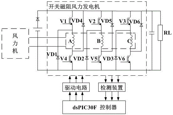
[0019] The switched reluctance wind power generation system is mainly composed of six parts: wind turbine, excitation power supply, switched reluctance generator, power converter, controller and detection device, such as figure 1 shown. In this system, a wind turbine drives a switched reluctance generator to rotate, converting wind energy into mechanical energy. The power converter acts as a channel for energy conversion. In the excitation phase, the external DC power supplies power to the phase winding through the power converter; in the freewheeling phase, the phase winding feeds back energy through the power converter. The controller is the central part of the whole system, which captures signals such as wind speed, voltage, current and rotor position during system operation, and then comprehensively processes them to control the on and off of the main s...


PUM


Abstract

The invention discloses a maximum power tracking control method for a switched reluctance wind turbine system. An operation area of a wind turbine is divided into a constant power control area and a maximum power tracking area according to rotational speed-output power characteristic curves of the wind turbine at different wind speeds. A wind speed tracking control method is adopted in the constant power control area, and a control system observes the wind speed by the aid of a wind measuring device, then given power at the current wind speed is output according to the internally stored rotational speed-output power characteristic curves of the wind turbine at different wind speeds, and finally, the speed close to the maximum power point is quickly tracked through power closed-loop control. The system enters the maximum power tracking area after the power closed-loop control is stable. In the area, the system tracks the maximum power through variable-step climbing searching to realize rapidness and accuracy of tracking of the maximum power, and meanwhile, a stop measure and an error control mechanism are introduced to enhance the stability of the system. The maximum power tracking control method combines advantages of wind speed tracking control and climbing searching, so that the stability, accuracy and rapidness of the system are improved, and the method has good engineering application value.

Description

technical field [0001] The invention relates to a method for controlling maximum power tracking of a switched reluctance wind power generation system, which belongs to the technical field of wind power generation. Background technique [0002] Switched reluctance generator has a simple structure (no winding or permanent magnet on the rotor), low manufacturing cost, strong fault tolerance, high operating reliability, and high efficiency in a wide speed range. It is used in many occasions, especially in harsh environments such as wind power generation. At present, the maximum power tracking methods mainly include wind speed tracking control, speed feedback control and hill climbing search. The wind speed tracking control method uses the wind measuring device to observe the current wind speed, and then outputs the maximum power given value or the speed given value (optimum speed) corresponding to the maximum power according to the speed-power curve of the wind turbine at diffe...

Claims


Application Information

Patent Timeline
Patent Type & Authority Applications(China)
IPC IPC(8): G05F1/67
CPCG05F1/67
Inventor 陈昊窦宇宇王青杨明扬唐悦赵仁明颜爽齐亚文韩玉倩
Owner CHINA UNIV OF MINING & TECH
Why Eureka
Try Eureka