
Transmitting coil structure with high-quality factor and winding method thereof

A high quality factor, transmitting coil technology, applied in coil manufacturing, transformer/inductor coil/winding/connection, preventing/reducing unwanted electrical/magnetic effects, etc., can solve the problem of limited thickness, reduced system quality factor, Multi-magnetic loss and other problems, to achieve the effect of uniform magnetic field distribution, improved quality factor, and reduced blind area

Active Publication Date: 2016-08-10
NINGBO WEIE ELECTRONICS TECH CO LTD
View PDF6 Cites 14 Cited by
  • Summary
  • Abstract
  • Description
  • Claims
  • Application Information

AI Technical Summary

Problems solved by technology

When the double-layer shielding layer is closely attached to the magnetic field generating device, that is, the coil, the quality factor of the system will decrease. At the position close to the coil, the intensity of the alternating magnetic field is the highest, and the high-intensity alternating magnetic field will cause iron in this part There are more magnetic losses in the ferrite magnetic sheet, and due to the limited thickness of the ferrite magnetic sheet, after the ferrite magnetic sheet is shielded, there is still a considerable magnetic field that meets the second shielding layer, that is, the copper layer. Part of the residual magnetic field excites eddy currents in the copper layer and creates losses, which further degrades the quality factor of the system

Method used


Image

  • Transmitting coil structure with high-quality factor and winding method thereof
  • Transmitting coil structure with high-quality factor and winding method thereof
  • Transmitting coil structure with high-quality factor and winding method thereof

Examples


Embodiment Construction

[0026] Several preferred embodiments of the present invention will be described in detail below with reference to the accompanying drawings, but the present invention is not limited to these embodiments. The present invention covers any alternatives, modifications, equivalent methods and schemes made on the spirit and scope of the present invention. In order to provide the public with a thorough understanding of the present invention, specific details are set forth in the following preferred embodiments of the present invention, but those skilled in the art can fully understand the present invention without the description of these details.

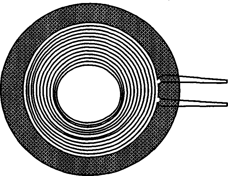
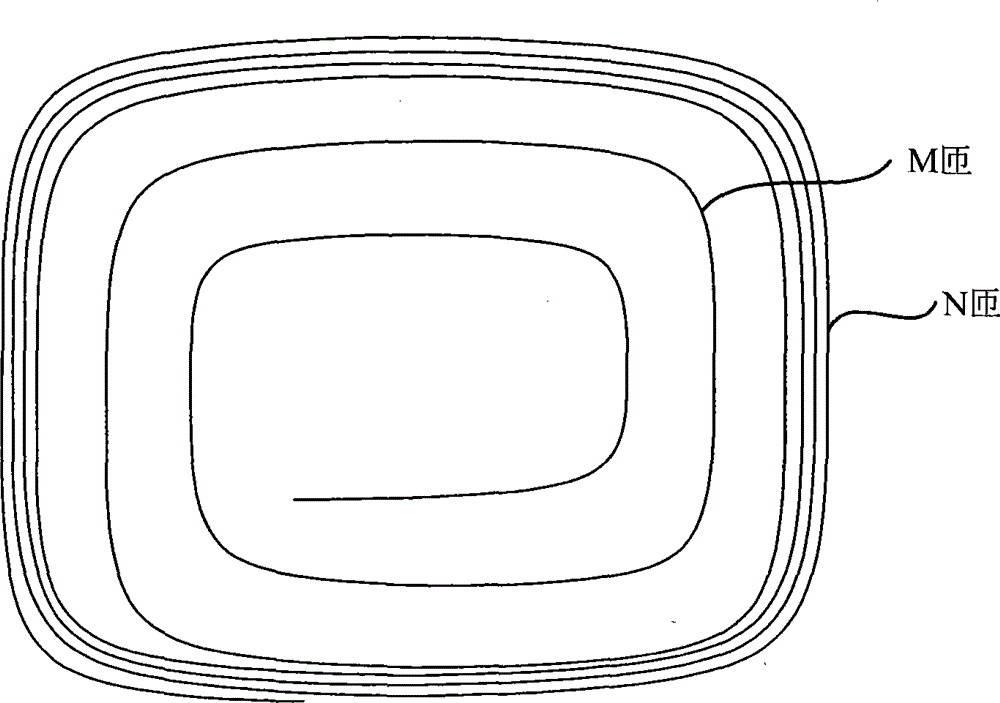
[0027] refer to image 3 Shown is a structural diagram of a transmitting coil according to the present invention, which is used in a wireless power transmission system for generating magnetic field energy transmitted to a secondary side. In an embodiment of the present invention, the transmitting coil includes a coil, an insulating layer...


PUM

PropertyMeasurementUnit
thicknessaaaaaaaaaa

Abstract

The invention discloses a transmitting coil structure with high-quality factor and a winding method thereof. A transmitting coil comprises a coil, an insulation layer attached to the coil and a shielding layer attached to the insulation layer. The coil is composed of M turns of loosely-intertwined winding wires and N turns of closely-intertwined winding wires. The spacing distance between turns of M turns of loosely-intertwined winding wires is larger than that between turns of N turns of closely-intertwined winding wires. M is less than N.The coil winding method thereof can help greatly the proximity effect of the coil, reduce loss and decrease the dead zone range of a magnetic field of the transmitting coil such that the quality factor of the transmitting coil is greatly increased. In addition, uniform magnetic field distribution is generated around the transmitting coil so that energy is effectively transmitted.

Description

technical field [0001] The invention relates to the field of wireless power transmission, more specifically, to a high-quality-factor transmitting coil structure and a winding method thereof. Background technique [0002] In a wireless power system, an induction coil (such as a transmitting coil) needs to be used to complete energy transmission. Since the transmitting coil is the source of excitation energy, its performance directly affects the efficiency of energy transmission. Therefore, try to improve the performance of the transmitting coil. The transmission efficiency of the whole system can be improved. Among the various parameters of the coil, the quality factor Q is an important index reflecting the performance of the coil. The higher the value of the quality factor Q, the smaller the coil loss, and the higher the efficiency. [0003] On the one hand, the Q value of the quality factor has a lot to do with the winding of the coil. At present, the winding of the induc...

Claims


Application Information

Patent Timeline
Patent Type & Authority Applications(China)
IPC IPC(8): H01F38/14H01F27/28H01F27/32H01F27/36H01F41/06H02J17/00
Inventor 钟霞
Owner NINGBO WEIE ELECTRONICS TECH CO LTD
Learn More