Filter and fly rod fastening structure thereof

A fastening structure and filter technology, applied in the direction of waveguide devices, connecting devices, electrical components, etc., can solve the problems that the coupling strength cannot meet the requirements, it is difficult to install the flying rod on the flying rod seat, and the coupling strength is affected. Reduce the chance of rework, make up for the size deviation of flying rods, and facilitate assembly

Inactive Publication Date: 2016-08-10
TONGYU COMM INC
View PDF5 Cites 10 Cited by
  • Summary
  • Abstract
  • Description
  • Claims
  • Application Information

AI Technical Summary

Problems solved by technology

see figure 1 and figure 2 , the fly rod 120 in the prior art is usually fastened in the filter cavity 130 by the fly rod seat 110, once the size of the fly rod 120 is determined, the coupling strength between the cavities 130 cannot be adjusted, because the coupling between the cavities 130 The strength is very sensitive to the size of the fly rod 120. In order to achieve a certain coupling strength, neither too weak nor too strong, the size of the fly rod 120 needs to be optimized repeatedly, but even if the appropriate size of the fly rod 120 is optimized, due to manufacturing and ass

Method used


Image

  • Filter and fly rod fastening structure thereof
  • Filter and fly rod fastening structure thereof
  • Filter and fly rod fastening structure thereof

Examples


Example Embodiment

[0031] The following describes the technical solutions in the embodiments of the present invention clearly and completely with reference to the accompanying drawings in the embodiments of the present invention. Obviously, the described embodiments are only a part of the embodiments of the present invention, rather than all the embodiments. Based on the embodiments of the present invention, all other embodiments obtained by those of ordinary skill in the art without creative work shall fall within the protection scope of the present invention.
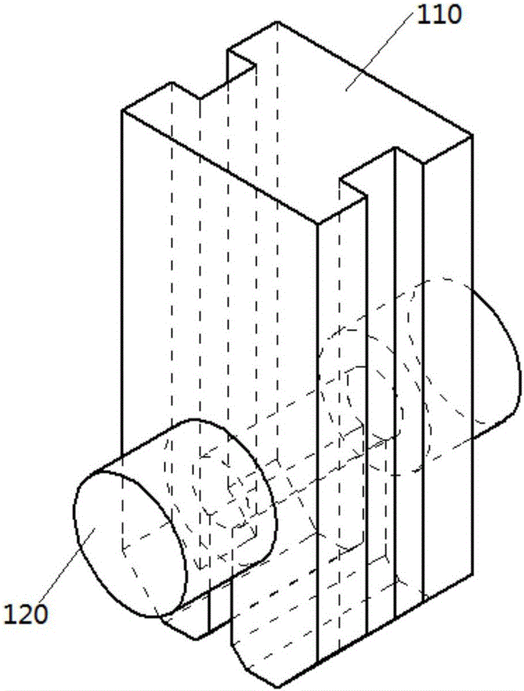
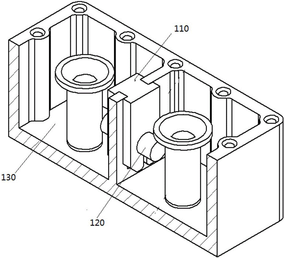
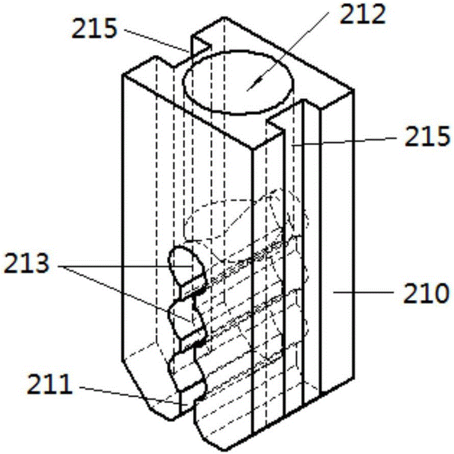
[0032] See Figure 3 ~ Figure 6 The fly rod fastening structure of the present invention includes a fly rod seat 210 and a fly rod 220. The fly rod seat 210 is a rectangular parallelepiped cylinder and can be made of plastic such as Teflon PTFE. There is an opening slit 211 extending along the length of the fly rod holder at the middle position of the lower end of the fly rod holder 210. A plurality of positioning holes 213 for fastening t...


PUM


Abstract

The invention provides a filter and its flying rod fastening structure. The filter includes a cavity and a cover plate. The cover plate covers the cavity to form a resonant cavity. The cavity is provided with ribs. The filter also includes a flying rod. A rod fastening structure, the flying rods of the flying rod fastening structure are installed on the ribs of the cavity. The fly rod fastening structure includes a fly rod seat and a fly rod. The lower end of the fly rod seat has an open slot extending along the length direction of the fly rod seat. The diameter of the positioning hole is larger than the width of the opening slit. At least one coupling hole is opened on the upper end of the fly rod seat, and the diameter of the coupling hole is larger than that of the coupling adjusting screw rod. The present invention performs rough adjustment of the coupling strength of the flying rod through the above-mentioned positioning hole, and then provides space for the fine adjustment of the coupling strength of the flying rod through the above-mentioned coupling hole, which is beneficial to the coupling of the flying rod after the installation of the flying rod or even after the cavity is installed. The strength is adjusted to a certain extent to compensate for the dimensional deviation of the fly rod due to assembly and manufacturing errors. The adjustment structure is simple, low in cost, convenient for assembly and debugging, can greatly reduce the probability of repair due to improper coupling of the fly rod, and improve the production pass rate.

Description

【Technical field】 [0001] The invention relates to a communication transmission component, in particular to a cavity filter and a fastening structure for a fly rod thereof. 【Background technique】 [0002] A filter is a frequency filtering device, which selects signals in the required frequency band and suppresses signals in the unnecessary frequency band. Filters are widely used in communication fields such as radio frequency and microwave. At present, the most widely used filter in the radio frequency and microwave frequency band is the coaxial cavity filter, which forms the desired working characteristics by adjusting the resonant frequency of multiple cavities and the coupling strength between the cavities. The adjustment of the resonant frequency of the cavity is generally accomplished by adjusting the depth of the tuning screw into the cavity, and the coupling between certain cavities is usually performed by controlling the size of the coupling fly rod. see figure 1 an...

Claims


Application Information

Patent Timeline
IPC IPC(8): H01P1/207H01P1/208H01P5/00H01P5/04
CPCH01P1/207H01P1/208H01P5/00H01P5/04
Inventor 蔡辉李桥吴中林肖杰李龙章高小鹏
Owner TONGYU COMM INC
Why Eureka
Try Eureka