Novel switch magnetic reluctance motor
A switched reluctance motor, a new type of technology, applied in magnetic circuits, electric components, electrical components, etc., can solve the problems of poor heat dissipation effect of the air gap between stator poles and rotor poles, inability to apply to high temperature environments, and threats to stable motor operation. Achieving good ventilation performance, improving heat dissipation effect, and the effect of noise without much change
- Summary
- Abstract
- Description
- Claims
- Application Information
AI Technical Summary
Problems solved by technology
Method used
Image

Examples
Embodiment 1
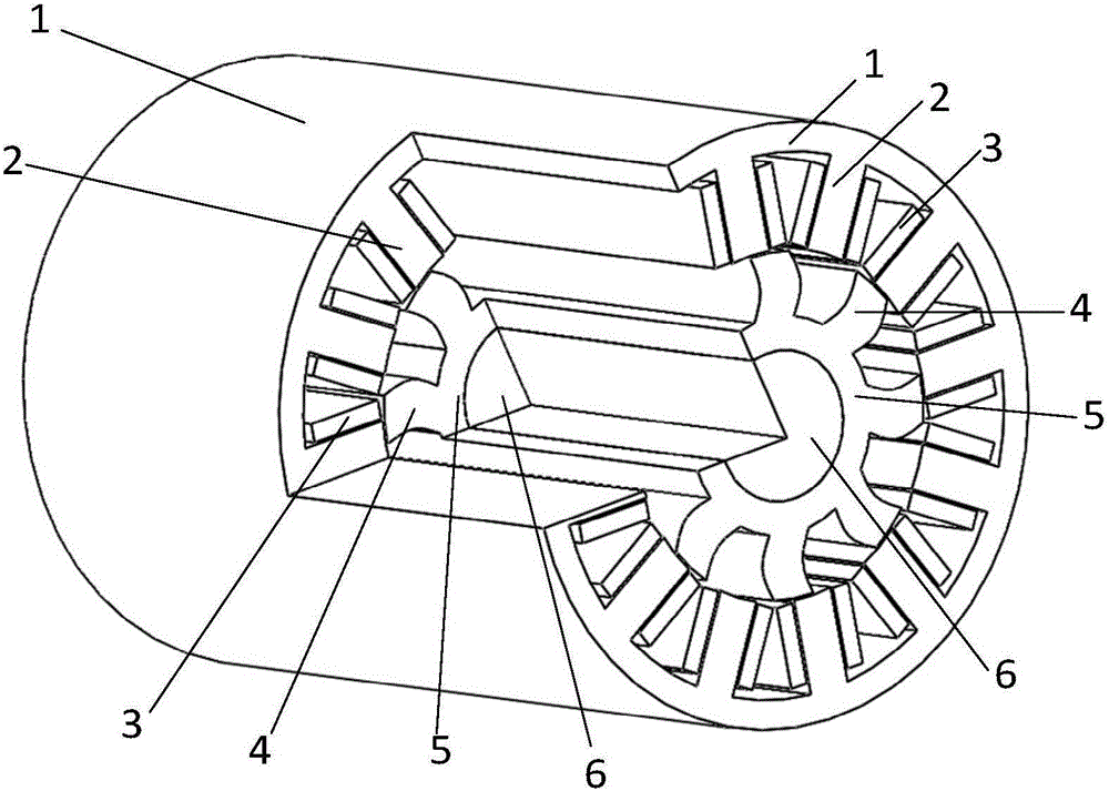
[0023] refer to figure 1 and figure 2 , the novel switched reluctance motor in this embodiment is mainly composed of a coaxially arranged rotating shaft 6, a rotor core and a stator core, and the remaining part in the middle is an air gap, and the stator core is made of an integrated stator pole 2 and The cylindrical stator yoke 1 is composed of the stator pole 2 and the stator yoke 1 laminated by silicon steel sheets. A number of stator poles 2 are distributed on the inner surface of the stator yoke 1 at equal intervals along the circumferential direction. The rotor core is made of An integral rotor pole 4 and a cylindrical rotor yoke 5 are formed. Several rotor poles 4 are distributed on the outer surface of the rotor yoke 5 at equal intervals in the circumferential direction. The rotating shaft 6 is magnetically conductive and runs through the rotor yoke 5. A stator winding 3 is provided in the gap formed between adjacent rotor poles 2 on the stator core. The stator windi...
Embodiment 2
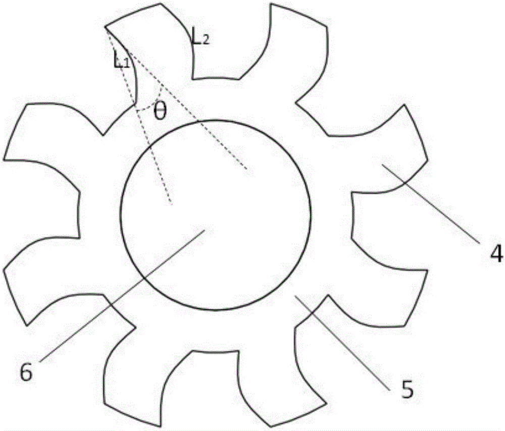
[0025] refer to image 3 The difference between this embodiment and the first embodiment is that the two sides of the rotor pole 4 protrude outward in an arc shape, and the two sides are arranged symmetrically with respect to the center of the rotor pole 4, and the two sides of the arc shape L 1 , L 2 Make the rotor pole 4 overall trapezoidal, and the included angle between the arc tangent line on the side of the rotor pole 4 and the vertical line between the upper and lower points on the same side is the deflection angle θ, and the deflection angle θ is 0° ~45°. With this setting, the vibration and noise of the motor are significantly improved, and the loss is also reduced under this scheme. Since the loss is reduced, the efficiency is improved, the heat density is reduced, and the temperature rise is reduced, so this structure is also applicable to the occasion in the first embodiment, and the loss is reduced and the power density is increased, which helps it carry a highe...
Embodiment 3
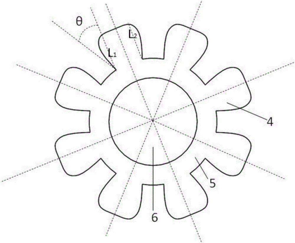
[0027] refer to Figure 4 , the difference between this embodiment and the first embodiment is that the two sides L of the rotor pole 4 1 , L 2 It is two straight lines inclined parallel to one side, and the angle between the side of the rotor pole 4 and the vertical line between the upper and lower points of the same side is the deflection angle θ, and the deflection angle θ is 0° ~45°. The vibration, noise, and temperature rise of the motor set in this way can be significantly improved. Based on the balanced performance of the structure on vibration, noise and temperature rise, it can be applied to more precise, complex and demanding occasions, such as military industry, aerospace and ships.
PUM
 Abstract
Description
Claims
Application Information