Cooling device for brushless vacuum cleaner motor

A technology for cooling devices and vacuum cleaners, applied in the direction of cooling/ventilation devices, electromechanical devices, electrical components, etc., can solve the problems of unfixed cooling gas flow, easy diffusion, and inability to effectively cool the motor temperature, so as to enhance the anti-demagnetization ability and reduce Case temperature, the effect of reducing the temperature

Active Publication Date: 2019-01-15
SUZHOU RUNHAO MOTOR CO LTD
View PDF6 Cites 0 Cited by
  • Summary
  • Abstract
  • Description
  • Claims
  • Application Information

AI Technical Summary

Problems solved by technology

[0005] The purpose of the present invention is to overcome the defects of the prior art that the flow direction of the cooling gas is not fixed, it is easy to diffuse, and cannot effectively cool the temperature of the motor, and to provide a device that reasonably guides the airflow of the motor fan of the vacuum cleaner, thereby effectively cooling the temperature of the motor of the vacuum cleaner

Method used


Image

  • Cooling device for brushless vacuum cleaner motor
  • Cooling device for brushless vacuum cleaner motor
  • Cooling device for brushless vacuum cleaner motor

Examples


Embodiment Construction

[0027] The technical solutions of the embodiments of the present invention will be clearly and completely described below in conjunction with the accompanying drawings of the present invention.

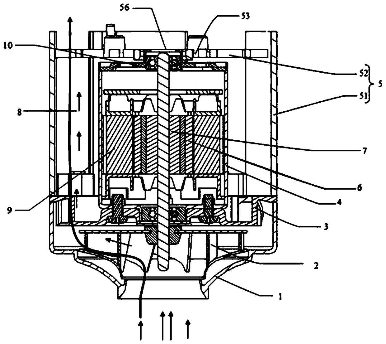
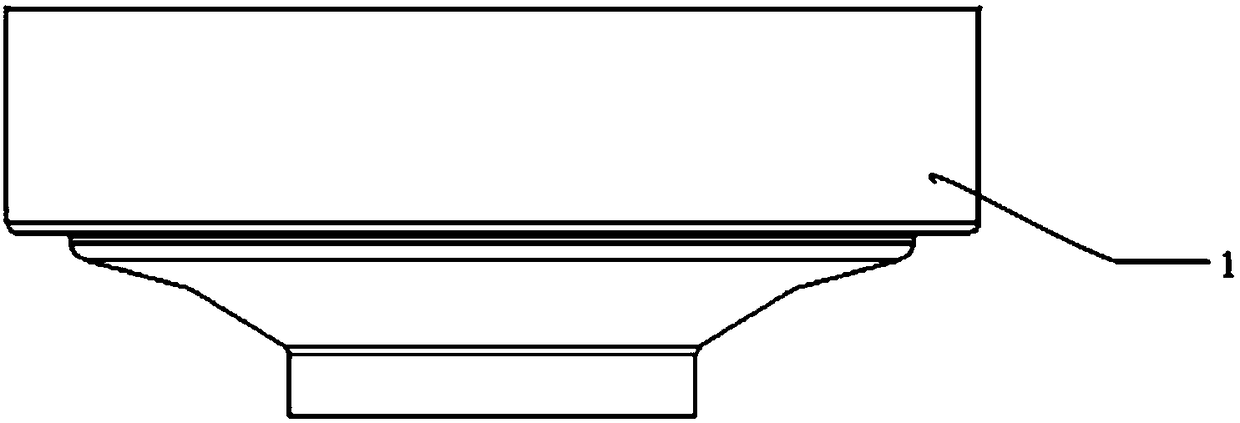
[0028] to combine figure 1 , figure 2 As shown, the cooling device of the brushless vacuum cleaner motor disclosed by the present invention includes a moving impeller wind cover 1, a moving impeller 2, a fixed impeller 3, a motor casing 4, and a motor wind cover 5 located outside the motor casing 4 , the moving impeller air cover 1 is arranged on the outside of the moving impeller 2, the fixed impeller 3 is installed on the motor casing 4, and the motor also includes a motor stator 6 and a motor rotor 7 arranged in the motor casing.

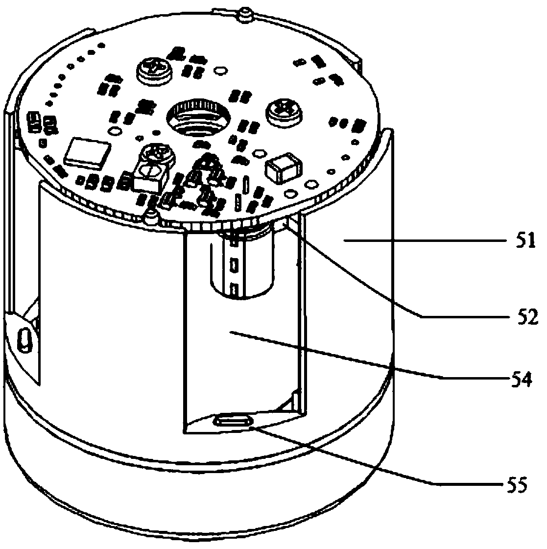
[0029] The motor wind cover 5 is sleeved on the outer peripheral side and one end side of the motor casing 4, and has a peripheral side portion 51 and an end portion 52. A gap 8 is provided between the peripheral side portion 51 and the outer periphera...


PUM


Abstract

The invention discloses a cooling device for a brushless motor of a vacuum cleaner, which includes a moving impeller wind cover, a moving impeller, a fixed impeller, and a motor casing, and the moving impeller wind cover is arranged on the outside of the moving impeller; the cooling device also It includes a motor fan cover arranged on the outside of the motor casing, the motor fan cover has an end part and a peripheral side part, a gap is provided between the peripheral side part and the motor casing, the moving impeller fan cover, the fixed An air flow channel is formed among the impeller, the motor fan cover and the motor casing. The invention can be used in various vacuum cleaner motors or similar motor structures, and has the advantages of rapidly reducing the heat of the motor, reducing the temperature of the casing, and the like.

Description

technical field [0001] The invention relates to the technical field of a brushless motor, in particular to a cooling device for a brushless vacuum cleaner motor. Background technique [0002] The vacuum cleaner is a cleaning appliance that uses a motor to drive the impeller to rotate at high speed to generate negative air pressure in the sealed housing, thereby sucking dust and other debris into the dust bag. The high-speed rotating rotor is easy to generate a lot of heat. Since most of the motors adopt a closed structure and there is no reasonable heat discharge device, the heat is easy to accumulate and not easy to dissipate. Eventually, the temperature of the enameled wire winding of the motor is much higher than the original one, and the insulation layer of the enameled wire is damaged. The service life will be shortened as the temperature increases, and the temperature of the motor casing will increase accordingly. [0003] The casing temperature of the motor is too hi...

Claims


Application Information

Patent Timeline
Patent Type & Authority Patents(China)
IPC IPC(8): H02K9/06H02K5/20
CPCH02K5/20H02K9/06
Inventor 尹凌飞
Owner SUZHOU RUNHAO MOTOR CO LTD
Why Eureka
Try Eureka