
Stub matching prefabricated form system used for corrugated steel web composite structure girder bridge

A corrugated steel web and short-line matching technology, which is applied in the field of bridge construction, can solve the problems of high installation and positioning accuracy of corrugated steel webs, difficult to guarantee the quality of concrete pouring, and complicated connection structure in the steel-concrete joint area, so as to ensure prefabricated construction. The effect of speed, easy assembly and disassembly, and high precision

Active Publication Date: 2016-08-10
CCCC SECOND HARBOR ENG +2
View PDF6 Cites 33 Cited by
  • Summary
  • Abstract
  • Description
  • Claims
  • Application Information

AI Technical Summary

Problems solved by technology

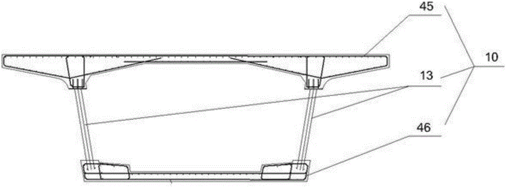
Compared with ordinary concrete segmental girder bridges, corrugated steel web composite segmental girder bridges increase the installation process of corrugated steel webs. Butt or lap joints are used between adjacent segments. The distance between the two ends of the corrugated steel web segment is usually less than 1cm from the fixed end form or the matching beam, while the distance between the two ends of the steel cage of the ordinary concrete segment is 1 cm from the fixed end form or the matching beam. With a protective layer thickness of 4-6cm, it is very difficult to enter the overall reinforcement cage of the corrugated steel web composite box girder section into the mold when the fixed end forms or matching beams at both ends of the section to be poured are positioned; in addition, the combination of steel and concrete The area connection structure is complex, the quality of concrete pouring is difficult to guarantee, and higher requirements are placed on formwork sealing

Method used


Image

  • Stub matching prefabricated form system used for corrugated steel web composite structure girder bridge
  • Stub matching prefabricated form system used for corrugated steel web composite structure girder bridge
  • Stub matching prefabricated form system used for corrugated steel web composite structure girder bridge

Examples


Embodiment Construction

[0057] The present invention will be further described in detail below in conjunction with the accompanying drawings, so that those skilled in the art can implement it with reference to the description.

[0058] It should be understood that terms such as "having", "comprising" and "including" as used herein do not entail the presence or addition of one or more other elements or combinations thereof.

[0059] It should be noted that the experimental methods described in the following embodiments, unless otherwise specified, are conventional methods, and the reagents and materials, if not otherwise specified, can be obtained from commercial sources; in the description of the present invention, The terms "landscape", "portrait", "top", "bottom", "front", "rear", "left", "right", "vertical", "horizontal", "top", "bottom", The orientation or positional relationship indicated by "inner", "outer", etc. is based on the orientation or positional relationship shown in the drawings, whic...


PUM


Abstract

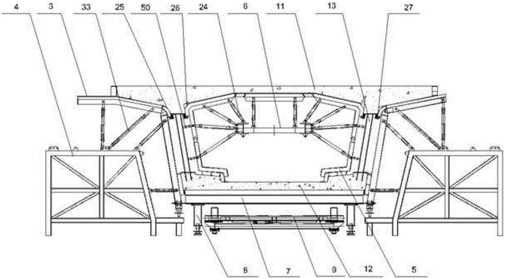
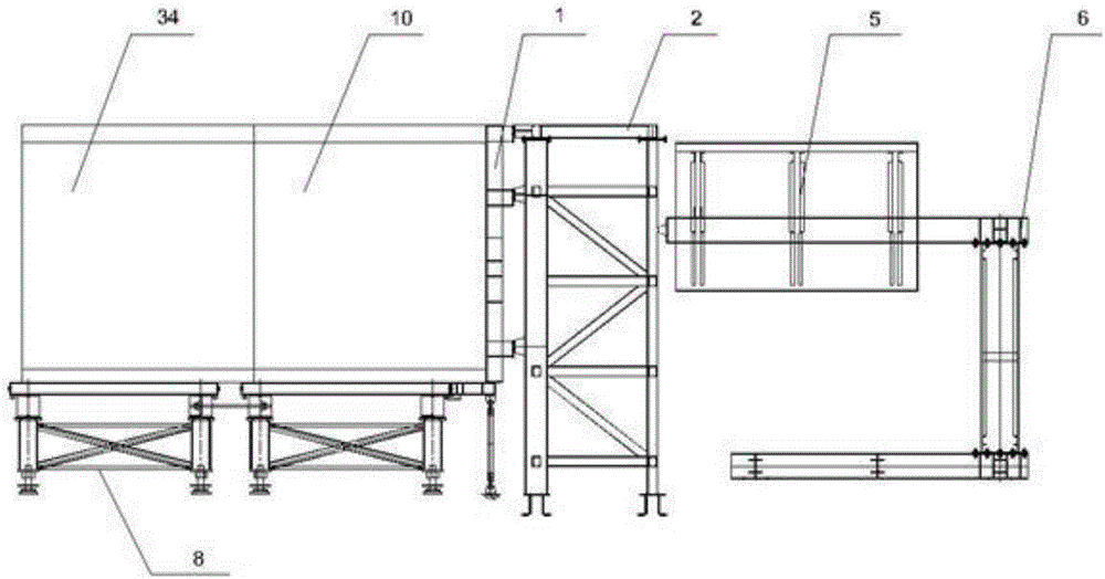
The invention discloses a stub matching prefabricated form system used for corrugated steel web composite structure girder bridge. The system includes a fixed end mould, a fixed end mould holder, an outer mould, an outer mould holder, an inner mould, an inner mould holder, a bottom mould, a bottom mould holder, a bottom mould trolley, a hydraulic system and the like. The fixed end mould includes an upper part and an under part, and a push-pull moving block which is convenient to enter mould for the corrugated steel web is disposed on the upper part opposite of the corrugated steel web. A three-way position adjustment device is disposed on a girder of the outer mould which accurately positions the space attitude of the corrugated steel web. A sealing device on steel-concrete composite is disposed on the steel-concrete composite area, and the device has the locate function of the corrugated steel web. The parts of the mould are assembled and accurately positioned by the hydraulic system according to the structure size of the girder sections. The system overcomes the problems that the installation accuracy requirement of the corrugated steel web is high and the reinforcement cage integral installation is difficult, and the prefabrication construction of the composite girder sections has high-quality and high-efficient.

Description

technical field [0001] The invention relates to the technical field of bridge construction. More specifically, the present invention relates to a stub matching prefabricated formwork system for corrugated steel web composite structural girder bridges. Background technique [0002] In recent years, bridges with corrugated steel web composite structures have been widely used in my country and even the world due to their light weight, high prestressing efficiency, good durability, and beautiful appearance. Pouring construction technology. With the development of bridge industrialization, the segmental precast assembly technology with the advantages of energy saving, environmental protection, high efficiency and durability has been promoted in concrete bridges. In addition to improving the construction quality and accelerating the construction speed, it can also improve the mechanical performance and seismic performance of conventional segmental beam joints, and reduce construc...

Claims


Application Information

Patent Timeline
IPC IPC(8): B28B7/00B28B7/28B28B17/00
CPCB28B7/0002B28B7/0011B28B7/0029B28B7/28B28B17/00B28B7/26
Inventor 张鸿张永涛陈鸣游新鹏王敏郑和晖黄跃巫兴发陈少林彭成明黄灿
Owner CCCC SECOND HARBOR ENG
Learn More