Microfluidic chip device and micro-fluid channel structure thereof

A technology of microfluidic channels and flow channels, applied in the field of microfluidics, can solve problems such as solid particle focusing, influence of solid particle physiological activity and functional state, unsatisfactory focusing effect of sheath fluid, etc.

Inactive Publication Date: 2016-08-17
GUANGDONG UNIV OF TECH +1
View PDF5 Cites 12 Cited by
  • Summary
  • Abstract
  • Description
  • Claims
  • Application Information

AI Technical Summary

Problems solved by technology

[0003] At present, in microfluidic technology, methods for focusing solid particles on microfluidic channels are generally divided into two types: active focusing and passive focusing. Among them, active focusing uses external forces (such as magnetic fields, electric fields, light, etc.) to manipulate solid particles. , but the external force will have a certain impact on the physiological activity and functional state of solid particles (such as biological particles, etc.), and will cause adverse effects on the detection structure; passive focusing includes sheath fluid focusing and Dean flow focusing, etc.
The focusing effect of the sheath liquid flow is not ideal, it is difficult to focus the solid particles on a single trajectory, and it is impossible to arrange the solid particles at equal intervals
[0004] Dean flow focusing is to use the centrifugal force generated when the solution flows in the asymmetric focusing bend to cause the secondary vortex to exert Dean drag force on the particles in the solution, and at the same time, the particles in the solution are also subjected to the inertial lifting force of the inertial flow. In this way, the solution The particles in the microfluidic channel are balanced at a fixed position through the combined action of the inertial lifting force and the Dean drag force, and the trajectories of particles of the same size are consistent under the same conditions, so the Dean flow focusing principle can be used Realize the movement of the same particle in the channel according to the same trajectory and arrange them in rows, so as to realize the inertial focusing of the particles, please refer to figure 1 , figure 1 It is a structural schematic diagram of an asymmetric focusing curve in the prior art. The above-mentioned asymmetric focusing curve 100 is composed of a plurality of large curves 110 and a plurality of small curves 120 connected alternately. The large curves 110 and small curves 120 The bending direction is opposite; but when the particle size of the solid particles is uneven, the Dean flow focusing cannot focus the particles of different particle sizes on the same straight line, and the focusing effect is poor

Method used


Image

  • Microfluidic chip device and micro-fluid channel structure thereof
  • Microfluidic chip device and micro-fluid channel structure thereof
  • Microfluidic chip device and micro-fluid channel structure thereof

Examples


Embodiment Construction

[0033] The invention provides a micro flow channel structure to achieve the purpose of making particles with different particle sizes on the same straight line and improving the focusing effect.

[0034] The following will clearly and completely describe the technical solutions in the embodiments of the present invention with reference to the accompanying drawings in the embodiments of the present invention. Obviously, the described embodiments are only some, not all, embodiments of the present invention. Based on the embodiments of the present invention, all other embodiments obtained by persons of ordinary skill in the art without making creative efforts belong to the protection scope of the present invention.

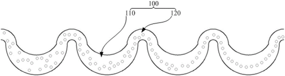
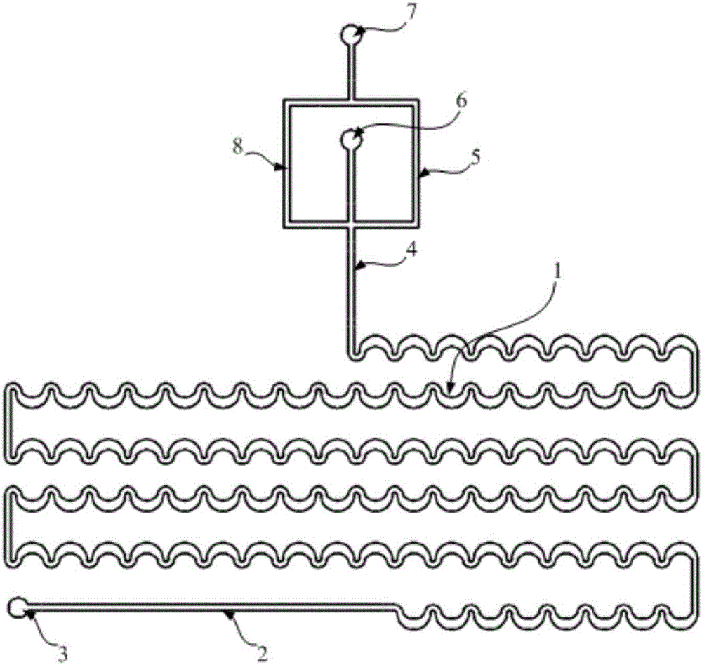
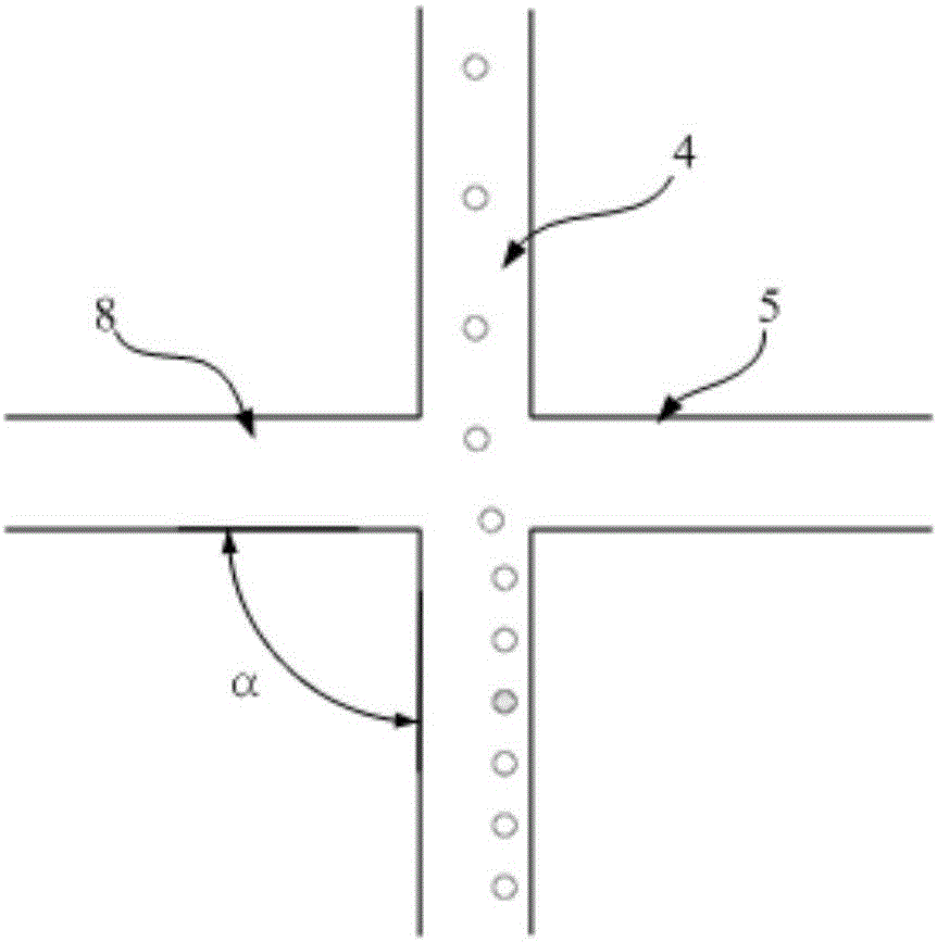
[0035] see figure 2 , figure 2 Schematic diagram of the microfluidic channel structure provided by the embodiment of the present invention.

[0036] A microchannel structure provided by an embodiment of the present invention includes an asymmetric focusing bend 1...


PUM

PropertyMeasurementUnit
Widthaaaaaaaaaa
Widthaaaaaaaaaa
Radius of curvatureaaaaaaaaaa

Abstract

The invention discloses a microfluidic chip device and its microchannel structure, wherein the microchannel structure includes an asymmetric focusing curve, a straight focusing channel and a sheath fluid channel, wherein the first of the asymmetric focusing curve One end communicates with the sample liquid inlet; the first end of the direct focusing channel communicates with the second end of the asymmetric focusing bend, and the second end communicates with the mixed solution outlet; the sheath fluid channel includes a left symmetrical channel about the direct focusing channel The flow channel and the right flow channel, the first ends of the left and right flow channels are connected with the sheath liquid inlet, and the second ends of the left flow channel and the right flow channel are respectively connected with the direct focusing flow channel from both sides; When in use, the sheath fluid focus and the Dean flow focus can be used to cooperate with each other. The particles of different particle sizes are first focused in the asymmetric focus bend to form a straight line, and then in the direct focus flow channel by two symmetrical sheath fluids. The second focusing function of the flow is all focused on the center line of the direct focusing flow channel, so as to achieve the purpose of improving the focusing effect.

Description

technical field [0001] The invention relates to the field of microfluidic technology, in particular to a microfluidic chip device and its microfluidic channel structure. Background technique [0002] Microfluidics is a technology that controls microfluidic flow on a very small scale. It can integrate a series of processes involved in chemistry and biology, such as sample preparation, chemical reaction, separation, and detection, into one with only a few square centimeters or even smaller chips. Since the microfluidic chip uses the flow properties of the fluid at the microscale to perform various operations, and uses various active or passive operating techniques to control the flow of the fluid inside the chip, the network formed by the microchannel makes the sample flow inside the chip The flow is in the condition of laminar flow and low Reynolds number to achieve the purpose of precise control of the sample. [0003] At present, in microfluidic technology, methods for fo...

Claims


Application Information

Patent Timeline
IPC IPC(8): B01L3/00
CPCB01L3/5027B01L2300/0832B01L2400/0412
Inventor 陈颖孙思帆成正东王超蔡小燕
Owner GUANGDONG UNIV OF TECH
Why Eureka
Try Eureka