
Cleaning drying device for refrigerating parts

A technology of drying device and accessories, which is applied in the directions of drying gas arrangement, cleaning method using liquid, cleaning method using gas flow, etc. , Improve cleaning efficiency, reasonable and compact structure design

Inactive Publication Date: 2016-08-17
ZHEJIANG XINCHANG SANRUI HORNSEY STAMPING IND
View PDF0 Cites 0 Cited by
  • Summary
  • Abstract
  • Description
  • Claims
  • Application Information

AI Technical Summary

Problems solved by technology

The traditional treatment method is to place the refrigeration accessories in the cleaning tank for cleaning and take them out to dry directly. During the drying process, there will be water flowing on the ground around the refrigeration accessories. The formed emulsion still adheres to the surface of fins or copper tubes, if it is not blown off with water in time, it will easily cause white spots on the surface of aluminum fins, corrode aluminum fins, and reduce product quality; The water adhered to the removed refrigeration accessories is not easy to fall due to the tension of the water surface, and part of it is evaporated naturally. After the water evaporates, only the emulsion is left on the surface of the fins. The surface cleaning is not thorough and the work efficiency is low. ; At the same time, after the cleaning is completed, the refrigeration accessories need to be moved to other locations for drying. The cleaning and drying process is more troublesome and takes up more space

Method used


Image

  • Cleaning drying device for refrigerating parts

Examples


Embodiment Construction

[0010] The present invention will be further described below in conjunction with the accompanying drawings.

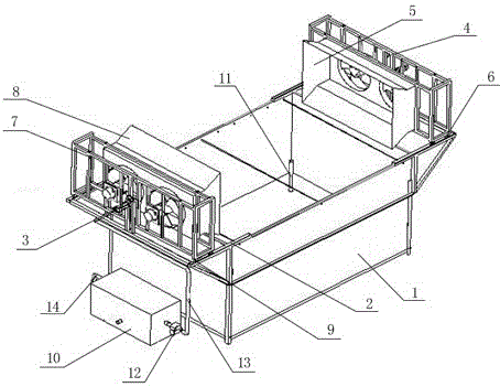
[0011] Such as figure 1 As shown, a cleaning and drying device for refrigeration accessories of the present invention includes a cleaning tank, a cold air device, an electric heating device, and an oil-water separator. 1. The chute 2, the cylinder 3, the chute 2 is set along the long axis direction of the upper end of the tank body 1, the two ends of the tank body 1 are fixed with the cylinder 3, the cylinder 3 is arranged perpendicular to the short axis direction of the tank body 1, the cooling air device and The electric heating device is arranged between the two cylinders 3, and the cold air device includes a first support 4 and a cooling fan 5 installed on the first support 4. The piston rod is connected, and a number of first rollers 6 are installed at the lower end and arranged in the chute 2; the electric heating device includes a second support 7 and a hot air...


PUM


Abstract

The invention discloses a cleaning and drying device for refrigeration accessories, which includes a cleaning tank, a cold air device, an electric heating device, and an oil-water separator. The cleaning tank includes a tank body, a chute, and a cylinder. The air cylinder, the cooling device includes a first support and a cooling fan, the first support is perpendicular to the upper end surface of the tank, and is connected with the piston rod of the cylinder on the same side, and a number of first rollers are installed at the lower end; the electric heating device includes a second support and a hot air blower, The second support is perpendicular to the upper end surface of the tank body, and is connected with the piston rod of the cylinder on the same side, and a plurality of second rollers are installed at the lower end; the oil-water separator is connected with the tank body through a degreasing water pipe. The invention integrates cleaning and drying into one, the structural design is reasonable and compact, and the tank body is connected with the oil-water separator, which can reduce the number of water changes in the cleaning process, and the setting of circulating pumps and circulating pipelines ensures water quality and facilitates cleaning of the surface of refrigeration accessories The adhering volatile oil and the setting of the sewage pipe are convenient to improve the cleaning efficiency.

Description

technical field [0001] The invention relates to a cleaning and drying device, in particular to a cleaning and drying device for refrigeration accessories. Background technique [0002] Refrigeration accessories usually need to be cleaned and dried after production. The traditional treatment method is to place the refrigeration accessories in the cleaning tank for cleaning and take them out to dry directly. During the drying process, there will be water flowing on the ground around the refrigeration accessories. The formed emulsion still adheres to the surface of the fins or copper tubes. If it is not blown off with water in time, it will easily cause white spots on the surface of the aluminum fins, corrode the aluminum fins, and reduce the product quality; The water adhered to the removed refrigeration accessories is not easy to fall due to the tension of the water surface, and part of it is evaporated naturally. After the water evaporates, only the emulsion is left to adso...

Claims


Application Information

Patent Timeline
Patent Type & Authority Applications(China)
IPC IPC(8): B08B3/10B08B3/14B08B5/02F26B21/00
CPCB08B3/10B08B3/14B08B5/02B08B2203/007F26B21/00
Inventor 陈均石丽腾
Owner ZHEJIANG XINCHANG SANRUI HORNSEY STAMPING IND
Learn More