Pipe expander for condenser

A condenser and tube expander technology, applied in heat exchange equipment, metal processing equipment, feeding devices, etc., can solve the problems of unguaranteed accuracy, low production efficiency, and heavy workload

Active Publication Date: 2016-08-17
CHANGZHOU CHANGZHENG HEAT EXCHANGER TECH
View PDF8 Cites 9 Cited by
  • Summary
  • Abstract
  • Description
  • Claims
  • Application Information

AI Technical Summary

Problems solved by technology

Existing tube expanders are used for large condensing tubes, but there is no corresponding equipment for some small condensing tubes. If the previous tube expanders are used to expand small condensing tubes, it will be overkill. , which has the effect of getting twice the result with half the effort, which not only increases the cost, but also reduces the production efficiency; even if there is a tube expander for small condensing tubes, there are still low production efficiency, low degree of automation, troublesome debugging, and workload Large, and the accuracy can not be guaranteed and other defects

Method used


Image

  • Pipe expander for condenser
  • Pipe expander for condenser
  • Pipe expander for condenser

Examples


Embodiment 1

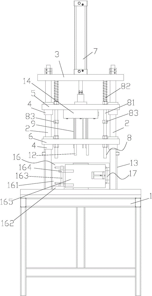
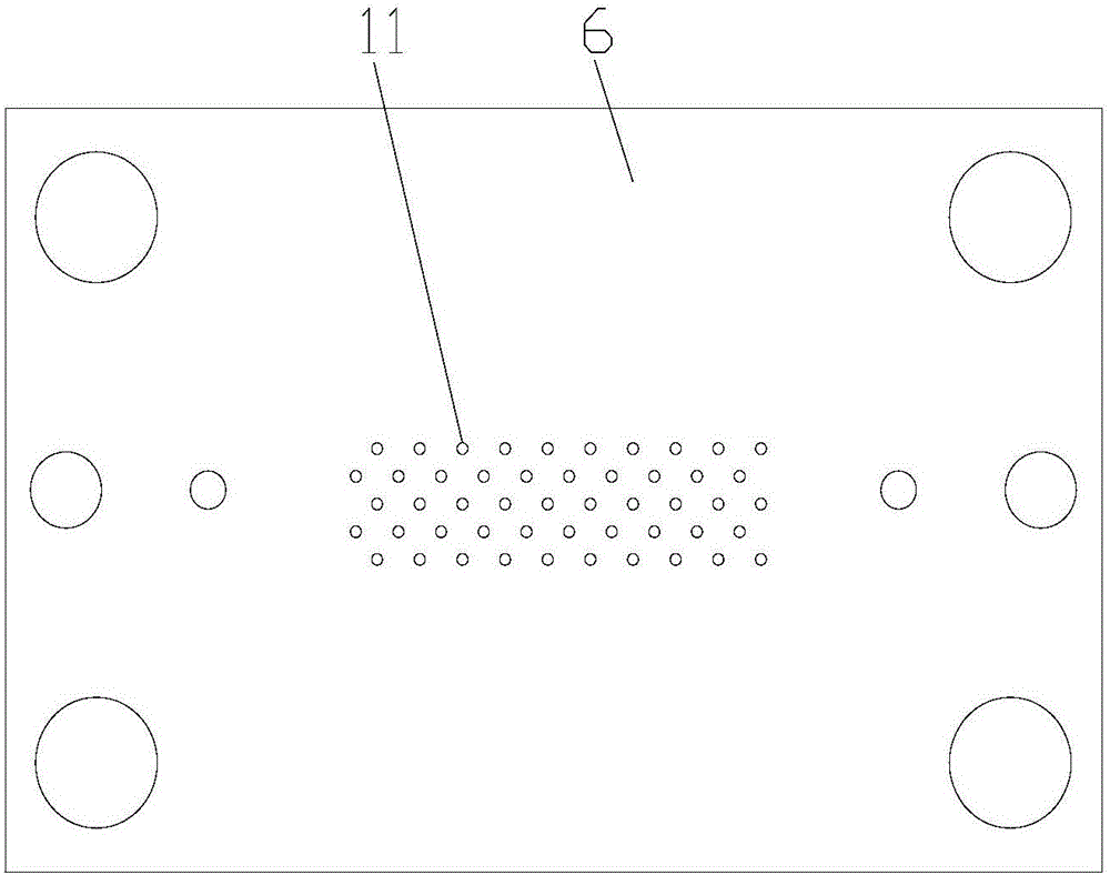
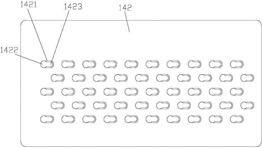
[0028] Example 1, such as Figure 1 to Figure 9 , a tube expander for condensers, including a frame 1, four fixed rods 2 are installed on the frame 1, the upper ends of the fixed rods 2 are connected with a mounting plate 3, and the lower part of the mounting plate 3 is provided with a set of guide sleeves 4 The cover plate 5 and the guide plate 6 on the fixed rod 2 are provided with an oil cylinder 7 for driving the cover plate 5 to move up and down on the mounting plate 3. Two buffer devices 8 are arranged between the plate 5 and the guide plate 6. The buffer device includes a screw 81 connecting the guide plate, the cover plate and the mounting plate, the screw rod is movably connected with the cover plate, and is fixedly connected with the guide plate and the mounting plate. A spring 82 sleeved on the screw rod is provided between the mounting plate and the cover plate, so that a safe distance can be kept between the cover plate and the mounting plate, and a stop nut 83 is...

Embodiment 2

[0034] Example 2, such as figure 1 , Figure 10 and Figure 11 , the above is to provide a way to clamp the condenser, now provide a way to compress the condenser, place the condenser on the frame and stick it to the rear baffle, turn the shaft to make the limit block press the condenser , the other end of the tailgate is provided with a pressing device 17 for pressing the limit block. The pressing device includes a connecting plate 171 vertically connected to the tailgate, and an upper slide is arranged on the connecting plate 171. Groove 176 and down groove 177, and upper chute and down chute are respectively provided with upper pressing plate 172 and lower pressing plate 173 parallel to tailgate, can realize compressing limit block 165 by upper pressing plate and lower pressing plate, described A gap is provided between the upper pressing plate and the lower pressing plate, a movable slide block 174 is provided in the gap, a pressing block 175 located in the gap is provid...


PUM


Abstract

The invention relates to a pipe expander for a condenser. The pipe expander comprises a rack, wherein a fixed rod is mounted on the rack; the upper end of the fixed rod is connected with a mounting plate; a cover plate and a guide plate which are arranged on the fixed rod in a sleeved manner through a guide sleeve are arranged below the mounting plate; a drive mechanism for driving the cover plate to move up and down is arranged on the mounting plate; a plurality of pipe expanding long rods are connected on the lower end surface of the cover plate; a plurality of pressure sleeves are fixedly arranged on the lower end surface of the guide plate; a limiting rod positioned below the guide plate is further arranged on the rack; the pipe expanding long rods are connected with the cover plate through a fixing device; guide holes adaptive to the pipe expanding long rods are formed in the guide plate; a clamping device used for fixing the condenser is arranged on the rack; and the clamping device is positioned below the guide plate. The pipe expander has the characteristics of being simple in structure, suitable for a small condenser, high in precision, high in production efficiency and the like.

Description

technical field [0001] The invention relates to the technical field of condenser manufacturing equipment, in particular to a tube expander for a condenser. Background technique [0002] The tube expander is a machine used to expand the diameter of many heat exchanger tubes placed in the heat sink, so that they can be tightly combined with the heat sink to avoid loosening and increase the thermal conductivity of the heat exchanger. Existing tube expanders are used for large condensing tubes, but there is no corresponding equipment for some small condensing tubes. If the previous tube expanders are used to expand small condensing tubes, it will be overkill. , which has the effect of getting twice the result with half the effort, which not only increases the cost, but also reduces the production efficiency; even if there is a tube expander for small condensing tubes, there are still low production efficiency, low degree of automation, troublesome debugging, and workload Large,...

Claims


Application Information

Patent Timeline
Patent Type & Authority Applications(China)
IPC IPC(8): B21D39/08B21D43/00B21D53/08
CPCB21D39/08B21D43/003B21D53/08
Inventor 陈建元
Owner CHANGZHOU CHANGZHENG HEAT EXCHANGER TECH
Why Eureka
Try Eureka