
Pipe cutting machine

A pipe cutting machine and frame technology, applied in the field of machinery, can solve problems such as high cost, inconvenient operation, and low work efficiency, and achieve the effects of reducing energy consumption, wide application range, and improving work efficiency

Inactive Publication Date: 2016-08-17
江方
View PDF6 Cites 7 Cited by
  • Summary
  • Abstract
  • Description
  • Claims
  • Application Information

AI Technical Summary

Problems solved by technology

[0003] Although the above-mentioned pipe cutting machine is simple in structure, more firmly fixed to the pipe fittings, and is very convenient to use, it still has the following problems: when cutting a pipe fitting with a larger diameter, since the diameter of the blade is smaller than the diameter of the pipe fitting, it is necessary to use the The pipe fittings can be cut by rotating circumferentially along their central axis. An additional clamping and rotating mechanism is required on the pipe cutting machine. Because some pipes have large diameters and long lengths, a high-power clamping and rotating mechanism is required to drive the pipes. Circumferential rotation, high cost and inconvenient operation; because only one blade is used in this pipe cutting machine to cut pipes from one direction, the working efficiency is low for large diameter pipes

Method used


Image

  • Pipe cutting machine
  • Pipe cutting machine
  • Pipe cutting machine

Examples


Embodiment Construction

[0029] The following are specific embodiments of the present invention and in conjunction with the accompanying drawings, the technical solutions of the present invention are further described, but the present invention is not limited to these embodiments.

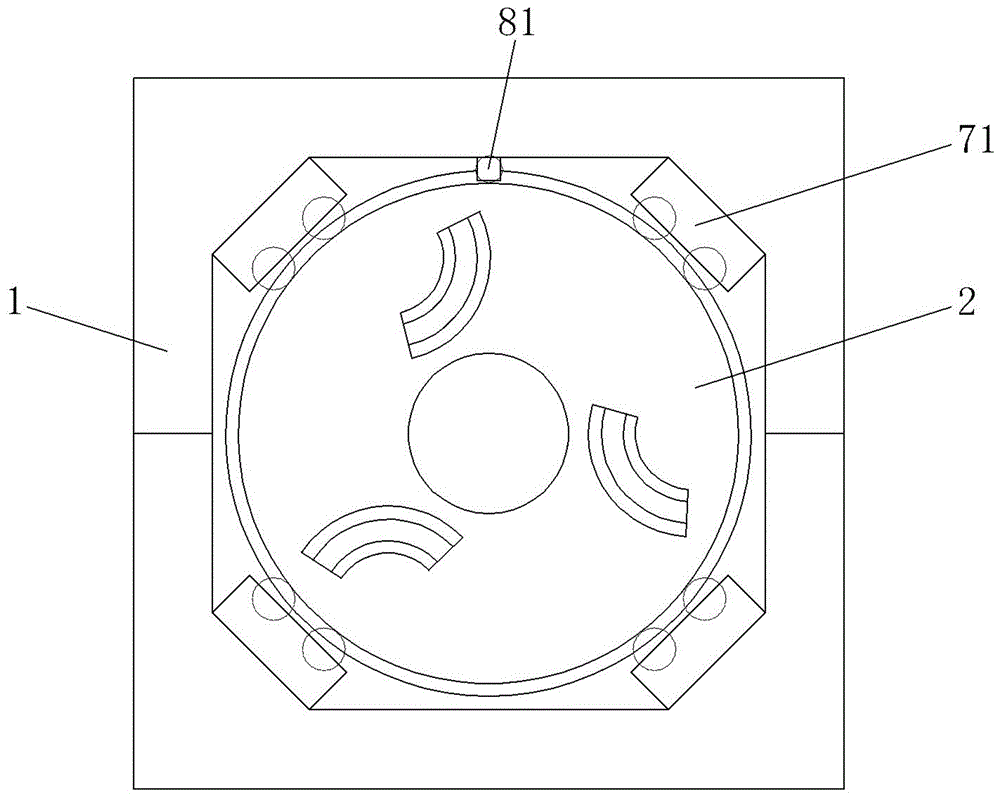
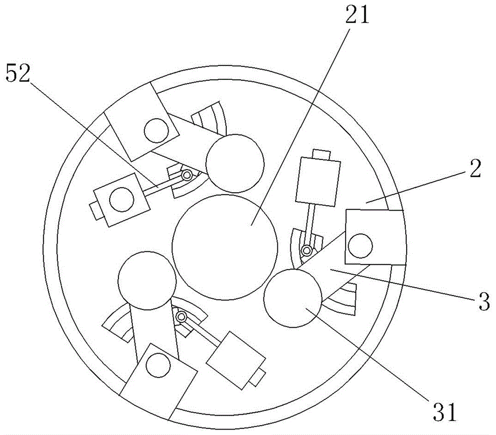
[0030] Such as figure 1 The shown pipe cutting machine includes a frame 1 and a turntable 2 vertically arranged on the frame 1. The middle part of the turntable 2 has a through hole 21 for pipe fittings to pass through. Between the frame 1 and the turntable 2 there is a As for the supporting structure of the turntable 2, the frame 1 is provided with a drive structure for driving the turntable 2 to rotate circumferentially along its central axis.

[0031] Specifically, the support structure includes 3-6 support 71 evenly arranged on the frame 1 and "I" type rollers 72 arranged on the support 71, such as figure 1 and Figure 7 As shown, there are four supports 71 in this embodiment and they are respectively located at the ...


PUM


Abstract

The invention provides a pipe cutting machine, and belongs to the technical field of machines. The pipe cutting machine solves the problems that an existing pipe cutting machine is small in application range and low in cutting efficiency. The pipe cutting machine comprises a machine frame and a rotating disc vertically arranged on the machine frame. A through hole for a pipe to penetrate through is formed in the middle of the rotating disc. A supporting structure used for supporting the rotating disc is arranged between the machine frame and the rotating disc. A driving structure used for driving the rotating disc to rotate circumferentially around the axis of the rotating disc is arranged on the machine frame. At least one swinging arm is arranged on the rotating disc, and blades used for cutting the pipe are arranged at the free ends of the swinging arms. Power units used for driving the swinging arms to swing around the hinged points of the rotating arms and the swinging arms are further arranged on the rotating disc, and under the action of the power units, the free ends of the swinging arms get close to or away from the pipe. The pipe cutting machine has the advantages of being convenient to operate, high in cutting efficiency and the like.

Description

technical field [0001] The invention belongs to the technical field of machinery and relates to a pipe cutting machine. Background technique [0002] During the processing of pipe fittings, subsequent welding, polishing, grinding and other processes need to be cut first. In the prior art, pipe fittings are mostly cut by pipe cutters. For example, a Chinese patent discloses a pipe cutting machine [the authorized announcement number is CN204545557U], which includes a body, the body is provided with a supporting wheel frame, the main vertical beam is movably connected with a support arm, the support arm is provided with a motor, and the motor and the blade drive connected; the support arm is provided with a hydraulic pump, and the hydraulic pump is provided with a pressure rod. When working, put the pipe fittings on the roller frame, swing the support arm to control the blade to cut the pipe fittings. [0003] Although the above-mentioned pipe cutting machine is simple in str...

Claims


Application Information

Patent Timeline
Patent Type & Authority Applications(China)
IPC IPC(8): B23D21/04B23D33/04
CPCB23D21/04B23D33/04
Inventor 江方
Owner 江方
Learn More