Crankshaft grinding machine servo center frame

A technology of crankshaft grinding machine and center frame, which is applied in the direction of grinding machines, grinding workpiece supports, and machine tools designed for grinding the rotating surface of workpieces, etc. It can solve the problem that the center frame cannot achieve the grinding accuracy of the crankshaft and the journal, and the deformation of the crankshaft, etc. problem, achieve the effect of preventing micro-deformation, protecting the crankshaft and ensuring stability

Active Publication Date: 2016-08-17
SICHUAN FEIYA AUTO PARTS CO LTD
View PDF11 Cites 5 Cited by
  • Summary
  • Abstract
  • Description
  • Claims
  • Application Information

AI Technical Summary

Problems solved by technology

Under the action of the self-weight of the crankshaft and the extrusion force of the grinding wheel, the crankshaft will be slightly deformed during the grinding process, and the support of the ordinary center frame cannot reach the grinding accuracy of the outer circle of the crankshaft and the journal.

Method used


Image

  • Crankshaft grinding machine servo center frame
  • Crankshaft grinding machine servo center frame
  • Crankshaft grinding machine servo center frame

Examples


Embodiment Construction

[0020] The present invention will be further described below in conjunction with accompanying drawing:

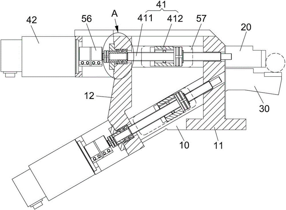
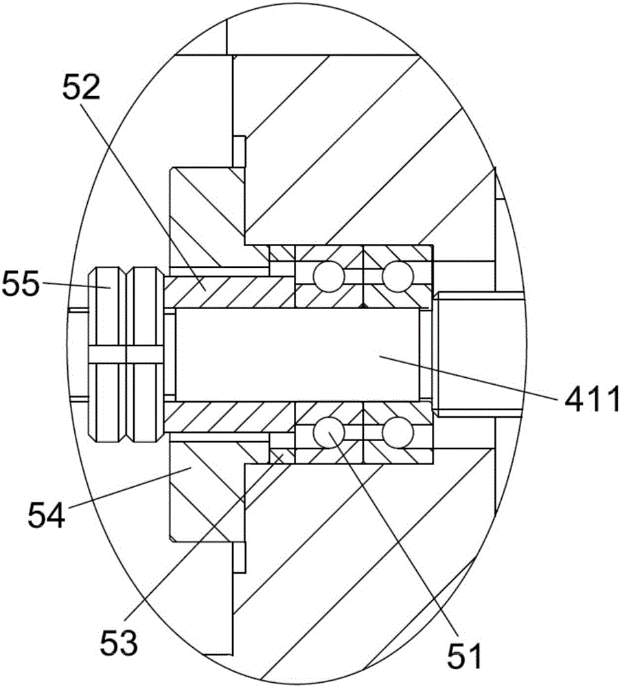
[0021] refer to Figure 1 to Figure 5 , The present invention provides a crankshaft grinder servo steady rest, including a bracket 10, a positioning rod 1 20, a positioning rod 2 30 and 2 sets of drive assemblies, and the positioning rod 2 30 includes an inclined driving section 31. The drive assembly includes a screw transmission mechanism 41 and a motor 42 that drives the screw transmission mechanism 41. The screw transmission mechanism 41 adopts a ball screw nut pair, which has high transmission efficiency and long life, and can realize micro-quantity and high-speed feeding; 42 adopts the servo motor 42 with self-locking function, and the servo motor 42 can correct and compensate the deformation of the crankshaft in real time;

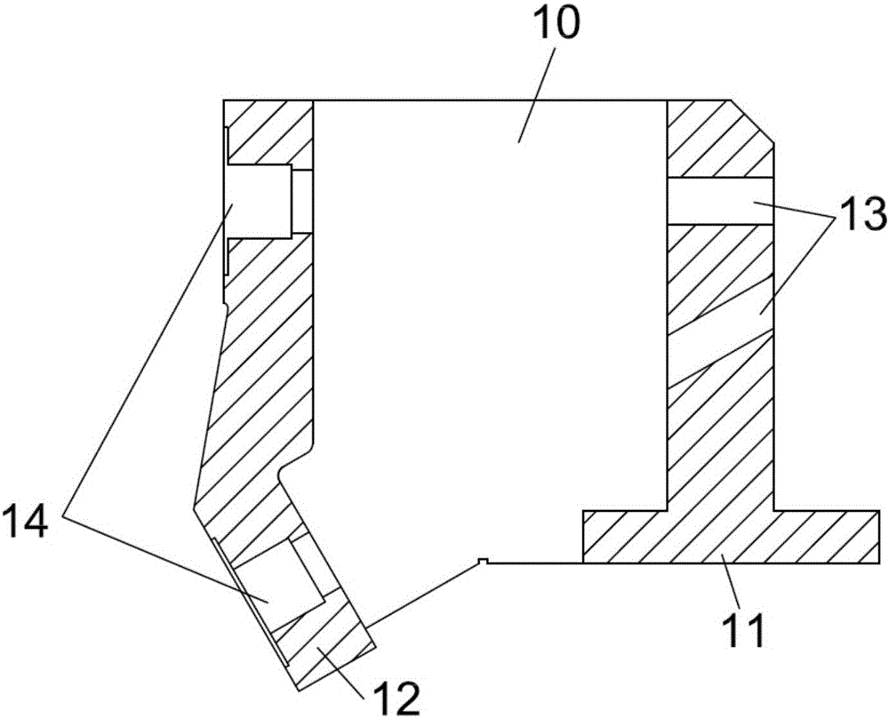
[0022] refer to figure 2 and image 3 The bracket 10 includes a support portion 11 and a positioning portion 12, the support portion 11 is p...


PUM


Abstract

The invention discloses a crankshaft grinding machine servo center frame comprising a supporting frame, a first positioning rod, a second positioning rod and two sets of driving assemblies. The second positioning rod comprises an inclined driving segment. Each driving assembly comprises a spiral transmission mechanism and a motor driving the spiral transmission mechanism. The first positioning rod is in the shape of a straight rod, a rod body of the first positioning rod is horizontally distributed, and the positioning end face of the first positioning rod is vertically distributed. The second positioning rod further comprises a supporting segment, and a supporting face of the supporting segment is arranged to be horizontal. An ejecting block is vertically distributed; a supporting block is horizontally distributed; a 90-degree included angle is formed between two positioning faces, the two positioning faces perform auxiliary positioning on a crankshaft jointly, deformation of the crankshaft under the effect of dead load can be prevented, and micro deformation of the crankshaft under extruding force of a grinding wheel of a grinding machine can be prevented as well; and servo motor drive and ball screw nut pair transmission are adopted, the changing extruding force of the grinding wheel of the grinding machine can be offset in real time in the grinding process, and the grinding precision required by an outer circle of a connection journal of the crankshaft is achieved.

Description

technical field [0001] The invention belongs to the technical field of auxiliary supports for crankshaft machining, and in particular relates to a crankshaft grinding machine servo steady frame. Background technique [0002] The outer circle of the crankshaft connecting rod neck can be processed on an ordinary grinding machine, mainly relying on the eccentric tooling at the head and tail of the bed to adjust the center of the outer circle of the connecting rod neck to coincide with the center of rotation of the main shaft of the grinding machine. Then place an ordinary center frame on the outer circle of the pin neck to be ground for auxiliary support to ensure the roundness and cylindricity of the outer circle of the pin neck after grinding. Under the action of the self-weight of the crankshaft and the extrusion force of the grinding wheel, the crankshaft will be slightly deformed during the grinding process, and the support function of the ordinary steady frame cannot reac...

Claims


Application Information

Patent Timeline
Patent Type & Authority Applications(China)
IPC IPC(8): B24B5/42B24B5/35B24B41/06
CPCB24B5/35B24B5/421B24B41/067
Inventor 文建军钟雪峰
Owner SICHUAN FEIYA AUTO PARTS CO LTD
Why Eureka
Try Eureka