
Feeding machine

A feeder and rack technology, applied in the field of feeder, can solve the problems of short lifespan and achieve the effects of overcoming short lifespan, avoiding slipping, and overcoming material leakage

Inactive Publication Date: 2016-08-17
MONALISA GRP CO LTD
View PDF9 Cites 3 Cited by
  • Summary
  • Abstract
  • Description
  • Claims
  • Application Information

AI Technical Summary

Problems solved by technology

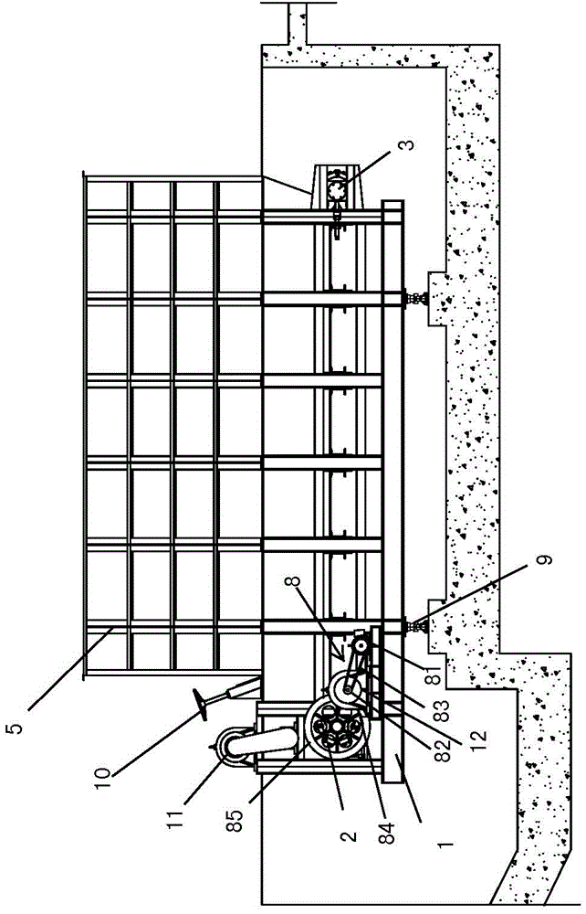
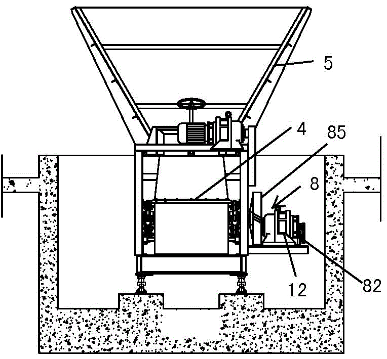
[0010] In view of the above, the technical problem to be solved by the present invention is to provide a feeder that can overcome the problems of material leakage and short life.

Method used


Image

  • Feeding machine
  • Feeding machine
  • Feeding machine

Examples


Embodiment Construction

[0050] The substantive features and significant progress of the present invention will be described below in conjunction with specific implementation forms and accompanying drawings. It should be understood that these embodiments are only used to further illustrate the present invention, and should not be construed as limiting the protection scope of the present invention.

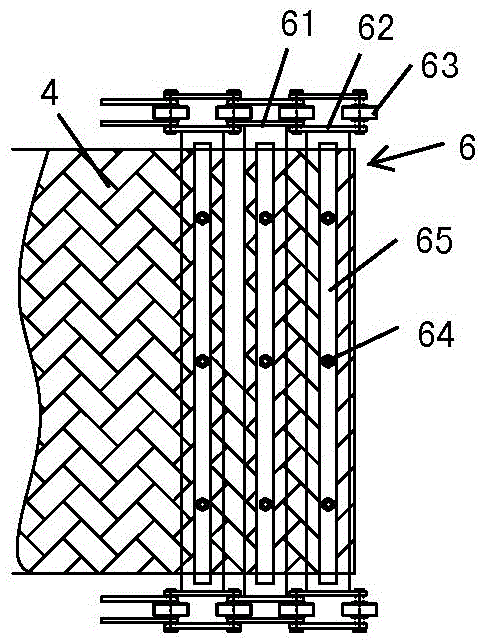
[0051] In order to solve the defects that the feeder in the prior art is prone to material leakage and short life when conveying materials, the present invention provides a feeder, comprising: a frame; A pair of driving gears for driving; a pair of driven gears arranged at the other end of the frame; a transmission belt wrapped around the driving gears and driven gears; and a hopper arranged above the transmission belt; The transmission belt is connected with the driving gear and the driven gear through a connecting mechanism to rotate with the rotation of the driving gear and the driven gear, and the conn...


PUM


Abstract

The invention provides a feeding machine. The feeding machine comprises a rack, a pair of driving gears arranged at one end of the rack and driven by a power device, a pair of driven gears arranged at the other end of the rack, a conveyor belt wound around the driving gears and the driven gears and a hopper positioned above the conveyor belt, wherein the conveyor belt is connected with the driving gears and the driven gears through a connecting mechanism so as to rotate with the rotation of the driving gears and the driven gears, the connecting mechanism comprises a connecting plate connected between the pair of driving gears or the pair of driven gears, the two ends of the connecting plate are separately connected with guide wheel assemblies arranged in the tooth spaces of the gears, and the conveyor belt is mounted on the connecting plate. The feeding machine can reduce friction resistance during running, improve the transmission efficiency of the conveyor belt and avoid slip phenomena, thereby overcoming the short service life problem of the existing feeding machine.

Description

technical field [0001] The invention relates to the field of ceramic tile manufacturing, in particular to a feeding machine. Background technique [0002] The manufacturing process of tiles generally includes material selection, batching, ball milling, powder spraying and granulation, pressing, green body drying, printing, kiln firing, polishing and edging, grading and packaging. Among them, the printed adobe is sent into the kiln for firing, and the adobe after leaving the kiln is the finished product (cooked adobe). Subsequently, the adobe can enter the polishing and edging process to further modify the adobe. [0003] In the manufacturing process of the above ceramic tiles, the existing feeding machine for ceramic tile production generally consists of three parts: electronic scales, transmission devices, and hoppers. In actual use, the raw materials used in tile production are added to the hopper of the feeder with the hopper of the forklift, and then the above-mentione...

Claims


Application Information

Patent Timeline
Patent Type & Authority Applications(China)
IPC IPC(8): B65G65/42B65G69/00
CPCB65G65/42B65G69/00
Inventor 萧礼标陈志坚麦仲铭黄玲艳
Owner MONALISA GRP CO LTD
Learn More