
A New Bottom Structure of Fluidized Chlorination Furnace Without Sieve Plate

A technology of boiling chlorination furnace and bottom structure, applied in the direction of titanium tetrachloride, titanium halide, etc., can solve the problem of hanging on the lower edge of the gas distributor or falling into the distributor, affecting the normal operation of the sieveless boiling chlorination process It is difficult to overcome the problems such as blockage of the gas outlet of the trachea, so as to extend the single working time, facilitate continuous and efficient production, and reduce the number and time of furnace shutdowns.

Inactive Publication Date: 2017-08-29
CHONGQING UNIV
View PDF4 Cites 0 Cited by
  • Summary
  • Abstract
  • Description
  • Claims
  • Application Information

AI Technical Summary

Problems solved by technology

Among them, the annular seam chlorine gas distributor [ 11 ] The application of the non-sieve-plate boiling chlorination furnace solves the uniformity of gas distribution in the furnace to a certain extent, but in the chlorination process, during the falling process of the caking material at the bottom of the sieve-free boiling chlorination furnace, some It will hang on the lower edge of the gas distributor or fall into the distributor, causing blockage in severe cases, thus affecting the normal operation of the non-sieve boiling chlorination process
Liu Yuming and others [ 12 ] A gas distributor for a boiling chlorination furnace without a sieve plate is proposed, which is a trachea-type chlorine distributor. This chlorine distributor can ensure the uniformity of chlorine gas distribution, but it is also difficult to overcome the technical problem of blockage of the gas outlet of the trachea.

Method used


Image

  • A New Bottom Structure of Fluidized Chlorination Furnace Without Sieve Plate
  • A New Bottom Structure of Fluidized Chlorination Furnace Without Sieve Plate
  • A New Bottom Structure of Fluidized Chlorination Furnace Without Sieve Plate

Examples


Embodiment Construction

[0054] The present invention will be further described in detail below in conjunction with the drawings. Among them, descriptive terms such as up, down, left, and right are used for the description, which aims to help readers understand, and are not intended to limit.

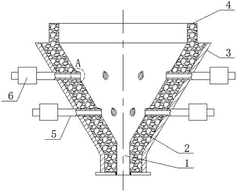
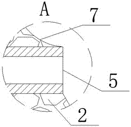
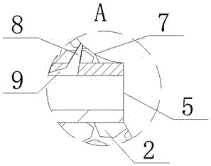
[0055] When implementing: Figure 1 to Figure 2 As shown, a new type of bottom structure of a sieve-free boiling chlorination furnace includes a shell 3 with a funnel shape. The bottom of the shell 3 has a slag discharge port 1, and the inner side of the shell 3 has an inner lining 2. And the inner liner 2 is made of high-temperature and corrosion-resistant materials; the outer shell 3 is sealed and fixedly provided with a circular nozzle 5, and the end face of the air nozzle of the circular nozzle 5 is a vertical circle. The air jet has an exposed part exposed outside the inner liner 2 and the lower end of the exposed part is flush with the surface of the inner liner 2.

[0056] In implementation, it is preferabl...


PUM


Abstract

The invention discloses a novel bottom surface of a fluidized bed chlorinator without a perforated plate. The novel bottom structure comprises a shell of a funnel shape, wherein a slag outlet is formed at the bottom of the shell; a lining layer is arranged on the inner side surface of the shell and made from a high-temperature resistant and anti-corrosion material; a circular spray pipe is fixed on the shell in a sealed penetration manner. The novel bottom structure is characterized in that the end surface of an air nozzle of the circular spray pipe is of a vertical circular shape; the air nozzle is provided with an exposure part exposed outside the lining layer; and the lower end of the exposure part is level with the surface of the lining layer. The bottom surface of the fluidized bed chlorinator without the perforated plate disclosed by the invention has the advantages of simple structure and skillful design, and can effectively relieve and even eliminate influence of a viscous material on the blockage of a gas distributor to improve gas distribution in the chlorinator; and moreover, the shutdown frequency and time are reduced, the single working time of the fluidized bed chlorinator is prolonged, and continuous efficient production of fluidizing chlorination is promoted.

Description

Technical field [0001] The invention belongs to the technical field of titanium tetrachloride preparation, and specifically relates to a novel bottom structure of a non-sieve plate boiling chlorination furnace. Background technique [0002] As an ideal structural material, titanium is widely used in aerospace, ships, weapons, chemicals, metallurgy, electric power, marine engineering, medicine, automotive sports goods, construction and other industries [ 1 , 2 ] . Titanium dioxide, as a white pigment with excellent properties, is used in coatings, inks, plastics, papermaking, chemical fiber, rubber and other fields [ 3 , 4 ] . Titanium sponge and titanium dioxide made of TiCl 4 Produced, so TiCl 4 It is an important intermediate raw material for titanium industrial production. [0003] Boiling chlorination method is the production of TiCl at home and abroad 4 The mainstream process of boiling chlorination is divided into sieve plate boiling chlorination method (ω(CaO+MgO)<1.5%) ...

Claims


Application Information

Patent Timeline
Patent Type & Authority Patents(China)
IPC IPC(8): C01G23/02
CPCC01G23/022
Inventor 白林陈登福范鹤林龙木军李元坤段华美温良英杜星宏
Owner CHONGQING UNIV
Learn More