Thermal insulation double-stop discharge sampling valve

A technology of sampling valve and discharge port, which is applied in the field of thermal insulation double cut-off discharge sampling valve, to achieve the effect of stable water flow in the pipe, simple structure and increased frequency

Inactive Publication Date: 2016-08-17
项敬来
View PDF5 Cites 0 Cited by
  • Summary
  • Abstract
  • Description
  • Claims
  • Application Information

AI Technical Summary

Benefits of technology

This patented design improves upon existing designs for draining fluid samples collected within a device called a thermo-insulating dual-cutting discharging sampling valving system (DISSV). It achieves this improvement because there is no complicated or expensive components needed compared to previous systems without these improvements. Additionally, the DISSIV uses a unique arrangement where both filters have their own functions such as filtering out unwanted particles while also allowing unfilterled water to pass through them effectively. Overall, the technical results include improved efficiency, reduced costs, better control of filtration quality, less damage caused by foreign objects, stable operation, prevention against leakage, and enhanced durability of the drainable material used in the device's housing.

Problems solved by technology

The technical problem addressed by this patented method is that conventional methods require samples or other steps at certain points along the pipeline before controlling how much material flows through them. This can lead to unsafe conditions when trying to stop something from moving too quickly due to insufficient pressure on some parts of the system caused by excessive fluid velocity. Additionally, traditional valves with filters are prone to damage if used frequently without proper maintenance.

Method used


Image

  • Thermal insulation double-stop discharge sampling valve
  • Thermal insulation double-stop discharge sampling valve
  • Thermal insulation double-stop discharge sampling valve

Examples


Embodiment Construction

[0022] The present invention will be described in further detail below in conjunction with the accompanying drawings.

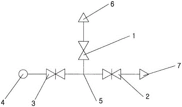
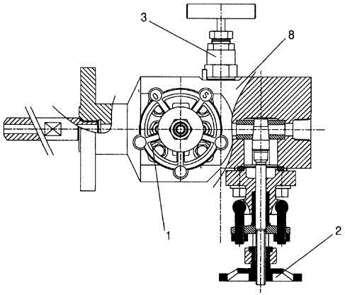
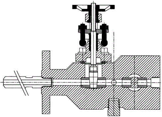
[0023] A thermal insulation double cut-off discharge sampling valve, such as figure 1 , figure 2 , image 3 As shown, it includes the main cut-off gate valve 1 and the valve body 8. The valve body 8 is provided with a valve body inlet 4. The valve body inlet 4 is connected to one end of the needle valve 3, and the other end of the needle valve 3 is connected to the T-shaped channel 5. The other two connecting ports of the T-shaped channel 5 are respectively connected with one end of the main cut-off gate valve 1 and the second cut-off gate valve 2; the other end of the main cut-off gate valve 1 is connected with the main discharge port 6; the other end of the second cut-off gate valve 2 Connected to outlet 7. In the actual implementation process of the patent, after the flow medium enters through the inlet 4 of the valve body, when sampling is not perform...


PUM


Abstract

The invention discloses a thermal insulation double cut-off discharge sampling valve, which comprises a main cut-off gate valve and a valve body. The valve body is provided with a valve body inlet, the valve body inlet is connected with one end of a needle valve, and the other end of the needle valve is connected with a T-shaped channel. The other two connecting ports of the T-shaped channel are respectively connected with one end of the main cut-off gate valve and one end of the secondary cut-off gate valve; the other end of the main cut-off gate valve is connected with the main discharge port; the other end of the secondary cut-off gate valve is connected with the discharge port connect. The invention has the beneficial effects of simple structure and low production cost; it is convenient to sample the flow medium during the flow process without affecting the flow medium. Moreover, the invention has a filtering function, and the valve core is not easy to be damaged.

Description


Claims


Application Information

Patent Timeline
Owner 项敬来
Why Eureka
Try Eureka