Pipeline pressure-stabilizing system and method used after liquefied petroleum gas out-conveying pipeline stops conveying

A technology for liquefied petroleum gas and pipelines, which is applied in the pipeline system, gas/liquid distribution and storage, mechanical equipment, etc. It can solve the problems of medium phase change in the pipeline, consume manpower and material resources, and difficult to establish a back pressure system to achieve a stable system Pressure, good safety, and the effect of increasing system pressure

Active Publication Date: 2016-08-17
BC P INC CHINA NAT PETROLEUM CORP +1
View PDF6 Cites 11 Cited by
  • Summary
  • Abstract
  • Description
  • Claims
  • Application Information

AI Technical Summary

Problems solved by technology

Although the above-mentioned problems can be alleviated by starting pigging or downstream tank truck suction after the shutdown, it brings difficulties in the source of pigging power, difficulty in establishing a back pressure system when restarting production, and phase change of the medium in the pipeline after pressure loss. Problems and hidden dangers will also consume a lot of manpower and material resources

Method used


Image

  • Pipeline pressure-stabilizing system and method used after liquefied petroleum gas out-conveying pipeline stops conveying

Examples


Embodiment Construction

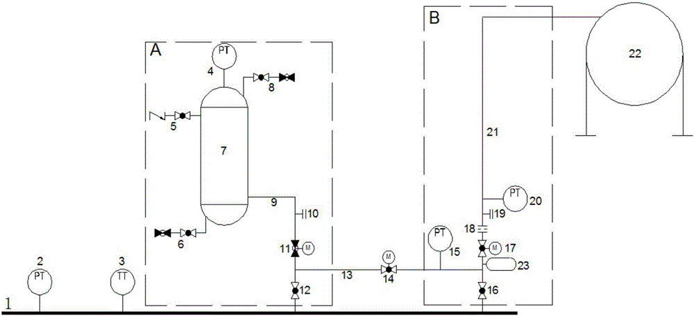
[0019] A pipeline stabilizing system after the stop of the liquefied petroleum gas pipeline, such as figure 1 Shown, including: main pipe short section 1, first pressure transmitter 2, temperature transmitter 3, second pressure transmitter 4, gas injection valve group 5, drain valve group 6, pressure buffer tank 7, exhaust Air valve group 8, discharge branch pipe 9, purge discharge port 10, stop valve 11, first cut off valve 12, connecting branch pipe 13, second cut valve 14, third pressure transmitter 15, third cut valve 16 , The fourth cut-off valve 17, the restrictive orifice 18, the purge port 19, the fourth pressure transmitter 20, the built-in liquefied petroleum gas storage tank 22 and the pressure buffer 23, etc., among them:

[0020] Second pressure transmitter 4, gas injection valve group 5, drain valve group 6, pressure buffer tank 7, exhaust valve group 8, discharge branch pipe 9, purge discharge port 10, stop valve 11, first cut off The valve 12 constitutes a first-...


PUM


Abstract

The invention discloses a pipeline pressure-stabilizing system and method used after a liquefied petroleum gas out-conveying pipeline stops conveying. The pipeline pressure-stabilizing system comprises a temperature sensor, a pressure sensor, a first-stage pressure-stabilizing device and a second-stage pressure-stabilizing device. The temperature sensor and the pressure sensor are arranged on a main pipeline short section, and the first-stage pressure-stabilizing device and the second-stage pressure-stabilizing device are connected with the main pipeline short section. The first-stage pressure-stabilizing device comprises a first block valve, a stop valve and a pressure buffering tank which are sequentially connected with the main pipeline short section. A second block valve is arranged between the first-stage pressure-stabilizing device and the second-stage pressure-stabilizing device. The second-stage pressure-stabilizing device comprises a third block valve, a pressure buffer, a pressure regulating device and a liquefied petroleum gas storage tank which are sequentially connected with the main pipeline short section. The temperature detection result obtained when conveying is stopped is compared with the ground temperature, the pressure change in the pipeline after a certain period is calculated, and the first-stage pressure-stabilizing device is used for carrying out pressure supplementation on the pipeline according to the analysis result, or the first-stage pressure-stabilizing device and the second-stage pressure-stabilizing device are used for releasing the pressure of the pipeline to achieve pressure stabilization of the pipeline after conveying is stopped, the system safety is guaranteed, and pigging and emptying of the whole line are avoided.

Description

Technical field [0001] The invention relates to a pipeline stabilization system and method after a liquefied petroleum gas external transmission pipeline is stopped. Background technique [0002] In recent years, with the rapid development of petroleum exploration and petrochemical industry, the production and utilization of liquefied petroleum gas have been improved day by day due to its high octane number, good anti-knock performance, and high calorific value. The pipeline transportation of liquefied petroleum gas has been vigorously developed after a lot of economic demonstration and scientific research. Since the density of liquefied petroleum gas is lighter in liquid than water, and heavier in air than air, and has extremely strong volatility, once pipeline leakage occurs, liquid phase vaporization and gas accumulation will inevitably occur, which is very easy to cause major accidents. [0003] In the traditional liquid phase pipeline transportation, the extreme pressure is t...

Claims


Application Information

Patent Timeline
Patent Type & Authority Applications(China)
IPC IPC(8): F17D1/02F17D3/01F17D5/00F17D5/02
CPCF17D1/02F17D3/01F17D5/005F17D5/02
Inventor 陈俊文杨帆郭艳林王磊缪晖汤晓勇胡连锋陈庆赵伏锐杨强马先代科敏明亮
Owner BC P INC CHINA NAT PETROLEUM CORP
Why Eureka
Try Eureka