Distance measuring device and distance measuring device method for realizing optical sampling by adjusting resonant cavity of femtosecond laser

A technology of femtosecond lasers and ranging devices, which is applied in the direction of measuring devices, instruments, and electromagnetic wave re-radiation, can solve the problems of low update rate, long scanning time, and no delay line, etc., to reduce ranging errors and data The effect of high update rate and high mechanical stability

Inactive Publication Date: 2016-08-17
TIANJIN UNIV
View PDF2 Cites 9 Cited by
  • Summary
  • Abstract
  • Description
  • Claims
  • Application Information

AI Technical Summary

Problems solved by technology

This approach has the following disadvantages: first, the system contains significant moving parts, and mechanical vibrations may destabilize the fringes; second, since the light pulses are spatially discrete, the collaborating mirror must be moved in order to find where the fringes appear , it takes a lot of effort; third, in order to perform arbitrary distance measurements, a larger scan range covering pulse-to-pulse intervals is necessary, which results in longer scan times and lower update rates, which cannot meet real-time measurements
This method achieves fast control of the time delay between two pulses by adjusting the repetition rate of the laser, and only requires one femtosecond laser, but inherits the main advantages of ASOPS: no movable delay line, high update rate and coverage of pulses and Scan range of pulse interval

Method used


Image

  • Distance measuring device and distance measuring device method for realizing optical sampling by adjusting resonant cavity of femtosecond laser
  • Distance measuring device and distance measuring device method for realizing optical sampling by adjusting resonant cavity of femtosecond laser
  • Distance measuring device and distance measuring device method for realizing optical sampling by adjusting resonant cavity of femtosecond laser

Examples


Embodiment

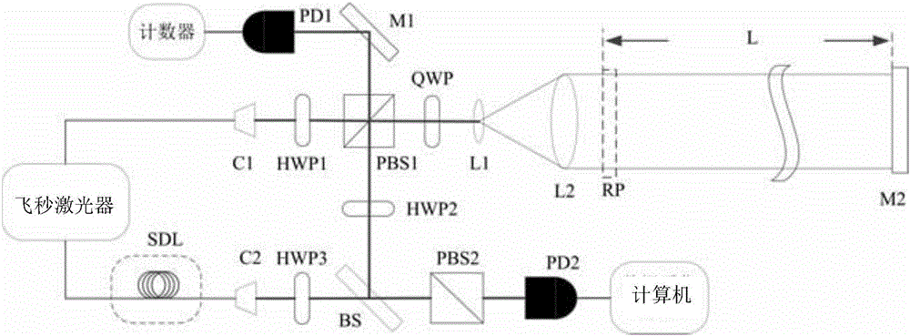
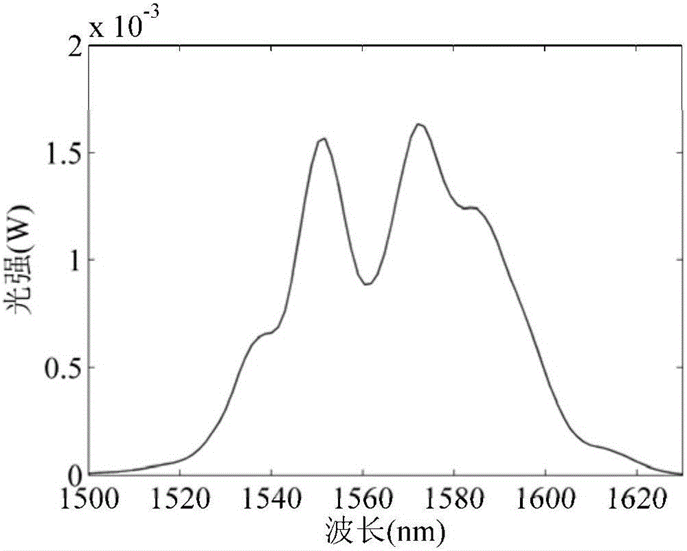
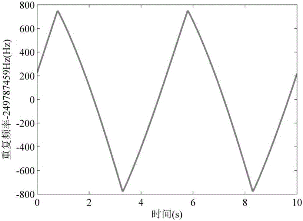
[0072] The central wavelength of the femtosecond laser is 1560nm, the pulse width emitted by the optical comb is 90fs, and the corresponding spectral width is about 55nm. According to the above-mentioned ranging steps, firstly, the second mirror M2 is placed at the reference position RP, and the Hilbert transform of the obtained time-domain cross-correlation fringes is obtained. In this embodiment, m=140 is calculated at the initial position, as shown in Figure 4 , 5 As shown in , 6, the instantaneous repetition frequency corresponding to the peak value of the envelope is 249.798428MHz. The second reflector is placed at the measurement position, and the Hilbert transform of the time-domain cross-correlation fringes is obtained, as Figure 7 , 8 As shown in , 9, the instantaneous repetition frequency corresponding to the peak value of the envelope is 249.798684MHz. At this time, the measured distance L is less than L pp / 2, m remains unchanged. The air group refractive in...


PUM


Abstract

The invention relates to a distance measuring method for adjusting a femtosecond laser resonator cavity to realize optical sampling. A reflector is placed at a reference position, and a computer collects cross-correlation fringes and repetition frequency changes at the same time, and Hilbert transforms the cross-correlation fringes. , find the instantaneous repetition frequency of the femtosecond laser corresponding to the highest point of the cross-correlation fringe envelope, the change of the repetition frequency is realized by adjusting the resonator of the femtosecond laser, at this time, the optical pulse of the signal source optical path and the local oscillator source optical path The light pulses are completely coincident, and the absolute distance of the reflector at the reference position is calculated. Then, the absolute distance of the second reflector at the position to be measured is calculated by the same method, and the measured distance is finally obtained. The invention utilizes a stable long optical fiber as a delay line, combines the pulse time-domain cross-correlation of a femtosecond laser, and realizes a ranging method and a ranging system for optical sampling by adjusting a resonant cavity, thereby effectively improving measurement accuracy.

Description

technical field [0001] The invention relates to a distance measurement method and a distance measurement system, in particular to a distance measurement method and a distance measurement system for realizing optical sampling by adjusting a resonant cavity with a femtosecond laser pulse suitable for absolute distance measurement. Background technique [0002] A femtosecond laser frequency comb is a device that locks the repetition rate and phase shift frequency of a femtosecond pulsed laser with a frequency reference source. In space, an optical frequency comb is a series of pulse sequences (with a pulse width of several femtoseconds), whose spectrum lines are arranged at equal intervals, and the frequency interval between adjacent spectral lines is equal to the repetition frequency. The spectral range covered by these spectral lines is several ten nanometers. Since the optical frequency comb is precisely locked to the time-frequency standard, all its spectral lines have the...

Claims


Application Information

Patent Timeline
Patent Type & Authority Applications(China)
IPC IPC(8): G01S17/32
CPCG01S17/32
Inventor 刘亭洋张福民吴翰钟曲兴华
Owner TIANJIN UNIV
Why Eureka
Try Eureka