Ring auxiliary type few-mode optical fiber for uncoupled mode-division multiplexing transmission and transmission method of ring auxiliary type few-mode optical fiber
A technology of few-mode fiber and mode division multiplexing, which is applied in the direction of graded-index fiber core/cladding fiber, cladding fiber, optics, etc. It can solve the problem of inapplicability, poor effective refractive index, and difficulty in effectively suppressing LP21 and LP02 Mode coupling and other issues, to achieve a good mode extinction ratio, increase the effective refractive index difference, and reduce the effect of preparation difficulty
- Summary
- Abstract
- Description
- Claims
- Application Information
AI Technical Summary
Problems solved by technology
Method used
Image
Examples
Embodiment 1
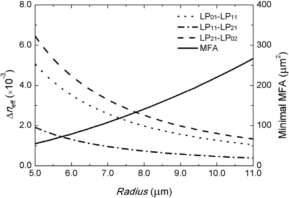
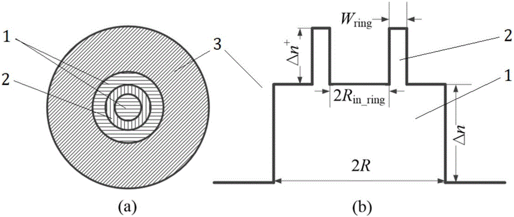
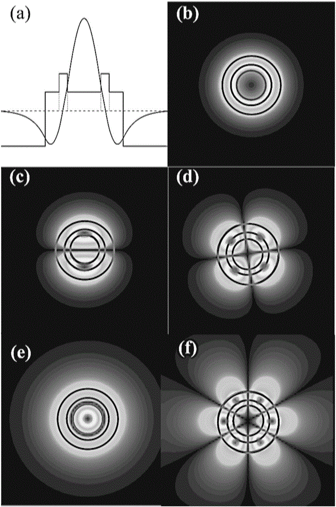
[0032] In this embodiment, a loop-assisted weakly coupled four-mode fiber is designed and optimized. To ensure four-mode operation and the highest order guided mode (LP 02 mode) capable of low-loss transmission, first study the possible core size and refractive index combination of the step-index fiber in the case of V = 5.1, and study their effective refractive index difference between modes at 1550nm and the mode field area with the fiber Variation of parameters. Such as figure 1 As shown in , while keeping the V value constant, as the core size increases, the effective refractive index difference of each mode decreases gradually, and the minimum mode field area of each mode increases significantly. Therefore, for the conventional step structure For few-mode fibers, there is an obvious mutual constraint relationship between the mode effective refractive index difference and the mode field area, and the limiting bottleneck is mainly LP 21 with LP 02 There is a small dif...
Embodiment 2
[0039] In this embodiment, a ring-assisted weakly coupled seven-mode fiber with grooves is designed. Fiber structure such as Figure 6 As shown in (a), the area indicated by the horizontal line is the core 1, the area indicated by the vertical line is the high refractive index ring 2 in the core, and the area indicated by the dot is the groove structure 4, which is used to compensate the bending loss. Such as Figure 6 As shown in (b), it is a schematic diagram of the refractive index distribution of the fiber section. It can be seen from the figure that the core diameter is 2R, the relative refractive index difference between the core and the cladding is Δn, and the inner circle diameter of the high refractive index ring in the fiber core is 2R in_ring , the radial width of the ring is W ring , the relative refractive index difference between ring and core is Δn + , a low-refractive-index groove is set between the core and the cladding, and the radial width of the groove i...
PUM
| Property | Measurement | Unit |
|---|---|---|
| Bending loss | aaaaa | aaaaa |
| Radius | aaaaa | aaaaa |
| Circle radius | aaaaa | aaaaa |
Abstract
Description
Claims
Application Information
 - R&D
- Intellectual Property
- Life Sciences
- Materials
- Tech Scout
- Unparalleled Data Quality
- Higher Quality Content
- 60% Fewer Hallucinations
Browse by: Latest US Patents, China's latest patents, Technical Efficacy Thesaurus, Application Domain, Technology Topic, Popular Technical Reports.
© 2025 PatSnap. All rights reserved.Legal|Privacy policy|Modern Slavery Act Transparency Statement|Sitemap|About US| Contact US: help@patsnap.com


