Unmanned aerial vehicle flight control system having multisensor redundant backup

A flight control system, redundant backup technology, applied in the direction of general control system, control/regulation system, non-electric variable control, etc., can solve the problems of aircraft normal flight influence, poor reliability, small size, etc., to improve the weight of flight control and cost, and the effect of improving reliability

Active Publication Date: 2016-08-17
ZHEJIANG UNIV
8 Cites 39 Cited by

AI-Extracted Technical Summary

Problems solved by technology

[0004] High-reliability sensors such as mechanical gyroscopes and fiber optic gyroscopes are heavy, bulky, and expensive, which limits their use on small UAVs
[0005] Most of the sensors that can be used on small UAVs are MEMS sensors, which are small in size, ligh...

Method used

With reference to accompanying drawing 1, a kind of unmanned aerial vehicle flight control system of multi-sensor redundant backup, described unmanned aerial vehicle flight control system comprises: be used for the main control unit that aircraft is controlled; For expanding main control unit Coprocessor unit for interface; redundant sensor unit for collecting aircraft data, including two or more accelerometers, two or more gyroscopes, two or more magnetometers, on...

Abstract

The invention relates to an unmanned aerial vehicle flight control system having multisensor redundant backup. The unmanned aerial vehicle flight control system can be used for multi-rotor unmanned aerial vehicles, helicopters and fixed wing unmanned aerial vehicles. The system is formed by a main control unit, a coprocessor unit, a sensor redundancy unit, a data exchange unit, a data recording unit and a power supply unit. The sensor redundancy unit is formed by multi-group gyroscopes, an accelerometer, a magnetometer, a magnetometer, a barometer and a satellite positioning system. A sensor fusion technology is applied, and when failures occur to a random single sensor, the sensor can be identified and isolated without causing influence on normal work of the flight control system. According to the unmanned aerial vehicle flight control system, on the premise that the increase of the flight control weight and the cost can be ignored relative to a whole, the reliability of the flight control system is greatly improved.

Application Domain

Technology Topic

Fixed wingData recording +15

Image

  • Unmanned aerial vehicle flight control system having multisensor redundant backup

Examples

  • Experimental program(1)

Example Embodiment

[0021] The present invention will be further elaborated and illustrated below in conjunction with the accompanying drawings and specific embodiments. The technical features of the various implementations in the present invention can be combined accordingly on the premise that there is no conflict with each other.
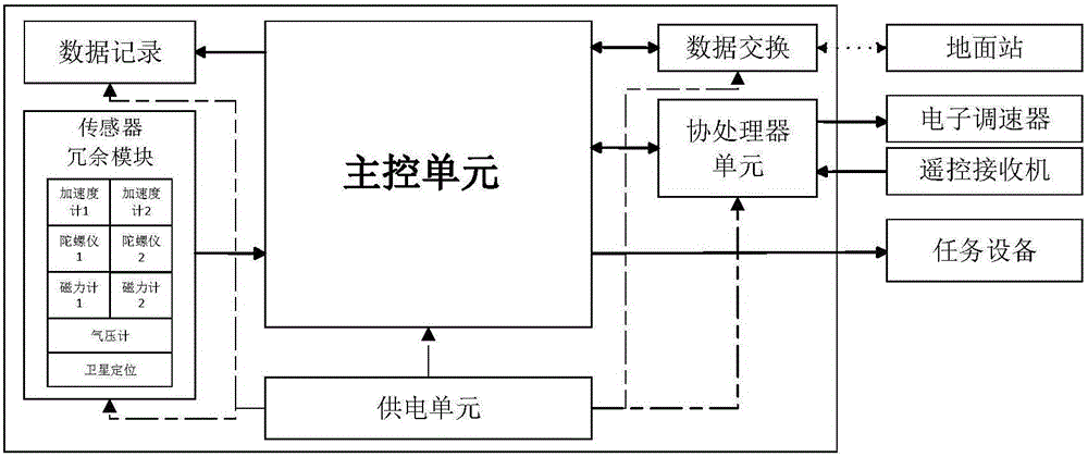
[0022] The multi-sensor redundant UAV flight control system of the present invention can be used for multi-rotor, helicopter, and fixed-wing UAVs. The system is composed of main control unit, coprocessor unit, sensor redundancy unit, data exchange unit, data recording unit and power supply unit. details as follows:
[0023] Refer to attached figure 1 , a UAV flight control system with multi-sensor redundant backup, the UAV flight control system includes: a main control unit for controlling the aircraft; a coprocessor unit for expanding the interface of the main control unit; Redundant sensor units for collecting aircraft data, including two or more accelerometers, two or more gyroscopes, two or more magnetometers, one or more altimeters, and one or more satellite positioning; redundant sensor units through Redundant backup of the same type of sensors and data fusion of different sensors to identify the failure of a single sensor and isolate it, thereby improving system reliability; power supply unit for powering the entire system; a data exchange unit; and a data recording unit for recording flight data.
[0024] The main control unit is used to control the aircraft and mission equipment; the main control unit obtains the raw data sensed by each sensor from the sensor unit, obtains the control signal of the ground station to the aircraft from the data exchange unit, and obtains the remote control signal from the co-processor unit (that is, the control signal forwarded by the remote control receiver); the main control unit performs navigation calculation according to the raw data sensed by the redundant sensor unit, and calculates the attitude, altitude, speed and position information of the aircraft; the result of the comprehensive navigation calculation, the ground The station control signal and the control signal sent by the remote control receiver are used to calculate the control rate, and the result of the calculation is sent to the coprocessor unit; at the same time, the control signal of the ground station to the mission equipment is obtained from the data exchange unit, and the mission equipment is controlled. The flight information of the aircraft is sent to the data exchange unit and the data recording unit; the main control unit is realized by any arithmetic unit among ARM, DSP and single-chip microcomputer.
[0025] The coprocessor unit is used to expand the interface of the main control unit; the coprocessor unit collects the control signal of the remote control receiver and transmits it to the main control unit; the coprocessor unit receives the control signals sent by the main control unit to each motor The signal is output to each electronic speed controller connected to the motor installed on the aircraft. The control signal of the remote control receiver is common multi-channel PWM or S.Bus of Futaba.
[0026] The redundant sensor unit is used to collect attitude, height, speed and position information of the aircraft.
[0027] The power supply unit is used to supply power to the entire system; the entire system includes a main control unit, a coprocessor unit, a sensor unit, a data exchange unit, and a data recording unit; the power supply unit is composed of a protection module and a transformer module.
[0028] The data exchange unit is used to transmit data with the ground station; the data exchange unit receives the flight information of the main control unit and sends it to the ground station, and at the same time receives the control information of the ground station to the aircraft and transmits it to the main control unit. The data exchange unit is realized by any one of a data transmission radio station, a bluetooth radio station, and a WIFI module.
[0029] The data recording unit is used to record the flight data of the aircraft; the data recording unit receives the flight data information sent by the main control unit and writes it into the memory chip.
[0030]The redundant sensor unit, by comparing the sensor data of the same type, makes a preliminary judgment on the sensor state, and when the data error is less than or equal to 10%, it is considered that the sensors are all working normally; Complementary fusion to determine whether it is faulty; if the number of each sensor is three or more, the sensor fault can be directly judged by the minority obeying the majority principle; if there are two of each sensor, the judgment method is as follows: If the accelerometer value If the difference is greater than 10%, determine which accelerometer is faulty by comparing its value with the satellite positioning position information after secondary integration; If the value difference is greater than 10%, it is judged which gyroscope is faulty by comparing the integrated value with the value of the magnetometer or accelerometer on the corresponding axis. The satellite positioning is one or a combination of GPS, Beidou, GLONASS, and Galileo.
[0031] The principle of the main control unit is to collect sensor data for navigation calculation, combined with control commands for control rate calculation, and finally output. The main control unit can collect sensor data from the redundant sensor unit through any one or more communication units of serial port, IIC, SPI, CAN, and apply the attitude fusion algorithm to perform navigation calculation according to the sensor data, and calculate the aircraft's navigation Information, the navigation information includes attitude, altitude, speed, and position information; according to the above navigation information, the control signal sent by the co-processing unit, and the ground station information sent by the data exchange unit, the control rate is calculated and the distribution is calculated. The control signal for each motor is sent to the co-processor unit, and the co-processing unit outputs it to the electronic speed controller that controls the motor; the main control unit also receives the control signal of the ground-to-task equipment from the data exchange unit. The mission equipment responds; the main control unit sends the flight data of the aircraft to the data exchange unit and the data recording unit respectively, the data sent to the data exchange unit will be sent to the ground station for display, and the data sent to the data recording unit will be written into the data Recording unit in the recording device SD card.
[0032] The power supply unit is used to first judge whether the polarity of the input voltage is correct and whether the range of the input voltage is correct. If the polarity and range of the input voltage are correct, then input it to the transformer module, and the transformer module converts it into the main Control unit, coprocessor unit, redundant sensor unit, data exchange unit, and data recording unit each require voltage to supply power for them.
[0033] The above-mentioned embodiment is only a preferred solution of the present invention, but it is not intended to limit the present invention. Various changes and modifications can be made by those skilled in the relevant technical fields without departing from the spirit and scope of the present invention. Therefore, all technical solutions obtained by means of equivalent replacement or equivalent transformation fall within the protection scope of the present invention.

PUM

no PUM

Description & Claims & Application Information

We can also present the details of the Description, Claims and Application information to help users get a comprehensive understanding of the technical details of the patent, such as background art, summary of invention, brief description of drawings, description of embodiments, and other original content. On the other hand, users can also determine the specific scope of protection of the technology through the list of claims; as well as understand the changes in the life cycle of the technology with the presentation of the patent timeline. Login to view more.

Similar technology patents

Classification and recommendation of technical efficacy words

Why Eureka
Try Eureka