Check patentability & draft patents in minutes with Patsnap Eureka AI!

Contact supporting assembly of direct-current contactor

A DC contactor and contact support technology, which is applied in the direction of relays, electrical components, electromagnetic relays, etc., can solve the problems that cannot meet the performance requirements of charging piles, improve contact support components, and complex processes, and achieve simplified pre-charging circuits. , reduce material costs, simplify the effect of processing technology

Active Publication Date: 2016-08-17
SHENYANG 213 CONTROL ELECTRICAL APPLIANCE MFG
View PDF5 Cites 5 Cited by
  • Summary
  • Abstract
  • Description
  • Claims
  • Application Information

AI Technical Summary

Problems solved by technology

Traditional DC contactors mainly include a base, contact support components, contacts for breaking circuits, and electromagnets, etc., while the contact support components in the prior art are not only complicated in process, but also can only close the active contacts, and have a single function , such as a push mechanism for a relay with patent number 201310282406.9
[0003] In recent years, although the DC contactors used in electric vehicles and electric-vehicle hybrid vehicles on the market meet the requirements of 320V for battery operation, they have not improved the contact support components and cannot meet the requirements of charging piles and electric vehicles. Requirements for further development and performance enhancement

Method used


Image

  • Contact supporting assembly of direct-current contactor
  • Contact supporting assembly of direct-current contactor
  • Contact supporting assembly of direct-current contactor

Examples


Embodiment 1

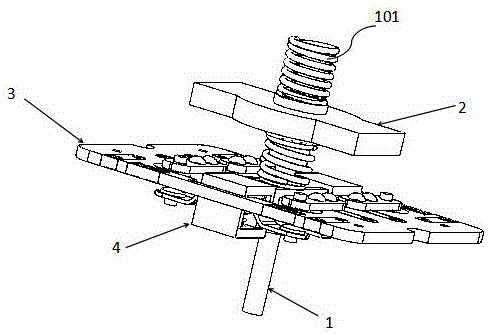
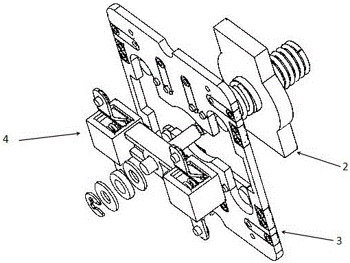
[0028] like figure 1 and 2 As shown, a contact support assembly of a DC contactor includes a push rod 1, a movable contact bridge assembly 2, a mounting plate assembly 3 and a support assembly 4; Made of magnetically conductive metal, the upper end of the push rod 1 is provided with a compression spring 101, and the compression spring 101 is placed on the open retaining ring and flat pad of the first slot of the push rod 1, and the compression spring 101 is pressed against the first position of the push rod 1. The opening retaining ring of a card slot is between the flat pad and the top end of the push rod 1 .

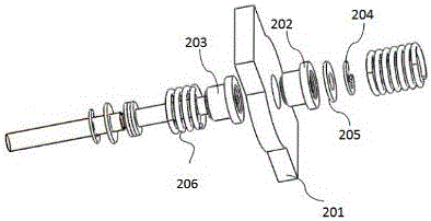
[0029] like image 3 As shown, the moving contact bridge assembly 2 includes an active contact 201, a spring seat and a contact spring 206, the active contact 201 is arranged between the first spring seat 202 and the second spring seat 203, and the active contact 201 passes through the first spring The seat 202 and the second spring seat 203 are sleeved into the pus...


PUM


Abstract

The invention relates to a contact supporting assembly of a direct-current contactor. The contact supporting assembly comprises a push rod, a movable contact bridge assembly, a mounting plate assembly and a supporting assembly, wherein the mounting plate assembly comprises a mounting plate, an auxiliary normally open static contact, a pre-charging static contact and a resistor; the supporting assembly comprises a supporting part, an auxiliary normally open movable contact and a pre-charging movable contact; the supporting part is arranged under the movable contact bridge assembly; the supporting part is fixed on the push rod; the normally open movable contact and the pre-charging movable contact correspond to the auxiliary normally open static contact and the pre-charging static contact respectively in position; and when the push rod is pushed, the movement distance of the movable contact bridge assembly is greater than the movement distance toward the pre-charging static contact of the pre-charging movable contact. With the adoption of the contact supporting assembly, the isolation between a movable contact bridge and the push rod and the auxiliary contacts and the push rod can be realized and the insulating performance of a product is improved; and the auxiliary contacts and the pre-charging contacts can also be integrated, so that the aims of simplifying a machining process and reducing the machining cost and the material cost are realized.

Description

technical field [0001] The invention relates to the field of low-voltage electrical appliances, in particular to a contact support assembly of a DC contactor. Background technique [0002] The existing single-pole DC contactor is mainly used for starting, stopping and power conversion circuit control of electric vehicles, electric forklifts and battery vehicles. The traditional DC contactor mainly includes a base, a contact support component, a contact for breaking the circuit, and an electromagnet, etc., while the contact support component in the prior art is not only complicated in process, but also can only close the active contacts, and has a single function. , such as a push mechanism for a relay with patent number 201310282406.9. [0003] In recent years, although the DC contactors that have been used in electric vehicles and electric vehicles in the market meet the requirements of 320V battery operation, they have not improved the contact support components and canno...

Claims


Application Information

Patent Timeline
IPC IPC(8): H01H50/54
CPCH01H50/54H01H50/541H01H50/546
Inventor 刘勇曹文宇赵磊葛鑫龙刘传亭
Owner SHENYANG 213 CONTROL ELECTRICAL APPLIANCE MFG
Features
  • R&D
  • Intellectual Property
  • Life Sciences
  • Materials
  • Tech Scout
  • Unparalleled Data Quality
  • Higher Quality Content
  • 60% Fewer Hallucinations
Learn More