Assembled type underground diaphragm wall and construction method thereof

A technology of underground diaphragm wall and construction method, which is applied in sheet pile wall, infrastructure engineering, construction and other directions, can solve the problem that the cast-in-place diaphragm wall structure cannot be improved or make up for quality defects, and affects the safety and waterproof effect of the diaphragm wall structure. , wall reinforcement cage structural damage and other problems, to achieve the effect of good project implementation, reliable component connection quality, and reduce project costs

Active Publication Date: 2016-08-24
SHANGHAI STRONG FOUND ENG +1
View PDF7 Cites 29 Cited by
  • Summary
  • Abstract
  • Description
  • Claims
  • Application Information

AI Technical Summary

Problems solved by technology

The cast-in-place underground diaphragm wall is currently the most widely used structural form, but it is often difficult to solve the stability of the trench wall and the stability of the trench during the construction of the underground diaphragm wall in the construction of underground diaphragm walls in complex geological conditions such as sandy soil layers. Concrete pouring quality problems caused by wall collapse, resulting in surface exposed bars and holes, local leakage of walls and joints, wall reinforcement cage structure damage and other wall quality defects, affecting the safety and waterproof effect of the underground continuous wall structure
[0003] Mud is used in the groove forming process of the underground diaphragm wall and the sup

Method used


Image

  • Assembled type underground diaphragm wall and construction method thereof
  • Assembled type underground diaphragm wall and construction method thereof
  • Assembled type underground diaphragm wall and construction method thereof

Examples


Embodiment Construction

[0030] In order to make the technical means, creative features, goals and effects achieved by the present invention easy to understand, the present invention will be further described below in conjunction with specific illustrations.

[0031] see figure 1 , figure 2 , image 3 , Figure 4 , Figure 5 and Figure 6 .

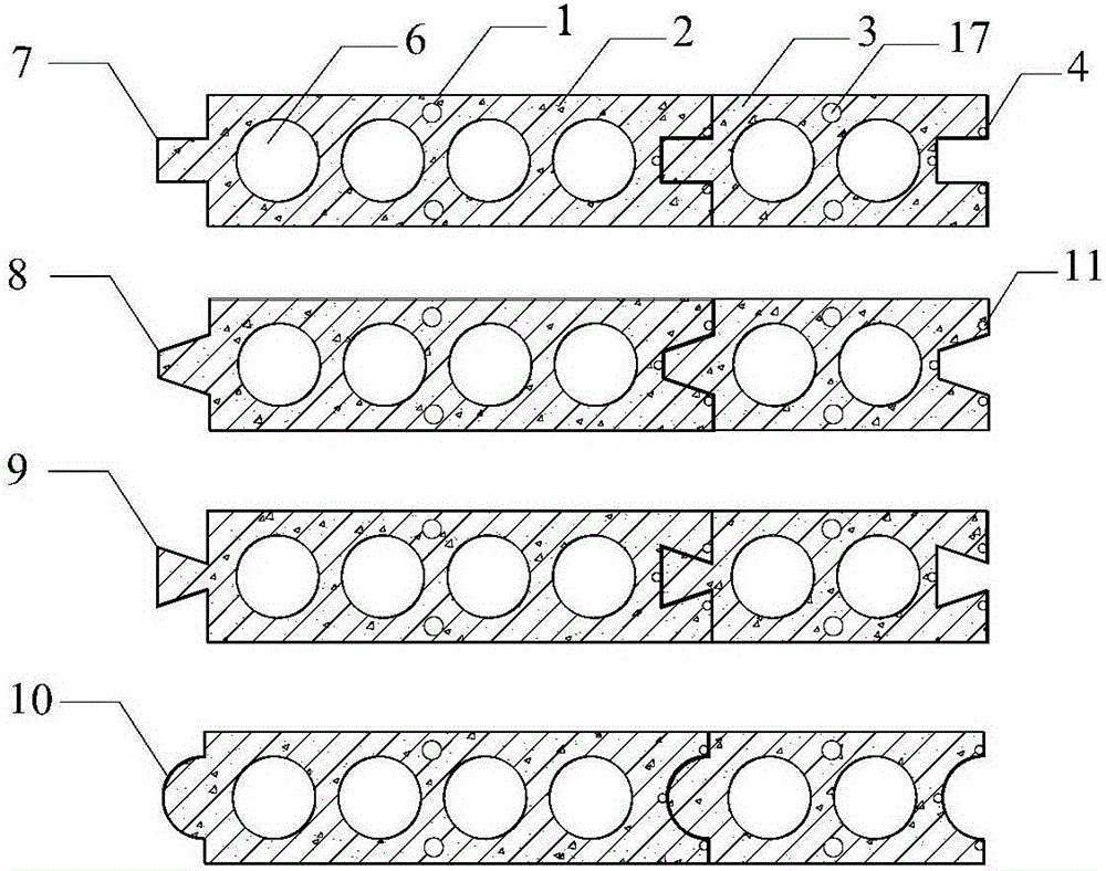
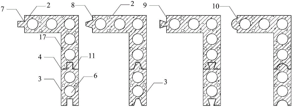
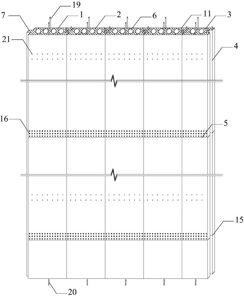
[0032] The prefabricated underground diaphragm wall structure is formed by splicing cavity diaphragm wall prefabricated components in the pre-excavated groove section through horizontal joints and vertical joints, including: the diaphragm wall prefabricated component 1 is composed of standard parts 2 and standard parts 3, The component 1 is provided with a vertical joint 4 and a horizontal joint 5, and a cavity 6 is provided in the middle of the prefabricated continuous wall component 1; the vertical joint 4 includes a concave-convex rectangle 7, a concave-convex trapezoid 7, a concave-convex inverted trapezoid 9, and a concave-convex arc 10; The vertical ...


PUM

PropertyMeasurementUnit
Thicknessaaaaaaaaaa

Abstract

The invention discloses an assembled type underground diaphragm wall. Diagram wall members are of cavity structures, and are prefabricated in a factory or at the construction site; the members are continuously spliced and connected in pre-dug trench sections; joints comprise transverse joints and vertical joints; the vertical joints are connected through tenons, and the transverse joints are connected through bolts in a staggering or tenoning manner; buried connection pieces are arranged on the side surfaces of the members; compact grouting pipes are arranged at the vertical joints of the members; grouting pipes are arranged in the members; hardcore beds for reinforcement are arranged at the bottoms of the members. According to the construction method, the prefabricated underground diagram wall members are assembled in the trench sections at the construction site, to form the underground diaphragm wall structure with both overall structure rigidity and anti-seepage performance according to vertical joint grouting, compact grouting at the bottom of the wall and gravel reinforcement. The construction method is high in construction controllability, high in quality, high in efficiency, short in period, low in engineering manufacturing cost and good in construction implementation effect, and materials can be saved.

Description

technical field [0001] The invention relates to the technical field of civil engineering, in particular to an assembled underground diaphragm wall structure for foundation pit enclosure and a construction method thereof. Background technique [0002] Diaphragm wall is the preferred structural form for deep foundation construction and deep foundation pit enclosure. It has been widely used all over the world. At present, underground diaphragm wall is replacing many traditional deep foundation and deep foundation pit enclosure structures and construction methods. The underground diaphragm wall has small vibration and low noise during construction, and is suitable for construction in densely populated areas of urban buildings; the wall has high rigidity and good anti-seepage performance; it can be applied to various geological conditions; it can be the permanent foundation of the upper structure; it can make full use of the building The limited ground and space within the red li...

Claims


Application Information

Patent Timeline
IPC IPC(8): E02D5/10E02D5/12E02D15/02
CPCE02D5/10E02D5/12E02D15/02
Inventor 刘全林丁勇春宋伟民刘忠池刘斐然张衡
Owner SHANGHAI STRONG FOUND ENG
Why Eureka
Try Eureka