Ignition coil for internal combustion engine and manufacturing method thereof

a technology of internal combustion engine and ignition coil, which is applied in the direction of transformer/inductance magnetic core, machine/engine, mechanical apparatus, etc., can solve the problems of vibration adversely affecting the electrical connection between external devices that are connected to the connector, cracks in the filler resin surrounding the core, and cracks in the filler resin disposed around the core, so as to achieve the effect of preventing cracking of the filler resin inside the case, reducing vibration, and flexible selection of th

Active Publication Date: 2019-06-20
DENSO CORP
View PDF0 Cites 5 Cited by
  • Summary
  • Abstract
  • Description
  • Claims
  • Application Information

AI Technical Summary

Benefits of technology

[0014]Additionally, a filler resin that is filled into a region on an outer side of the secondary coil being wound on the secondary a spool is different from a filler resin that is filled into other regions of the case. Also, flexibility in selecting a type of the first filler resin, which is disposed around the secondary coil that is wound around the secondary spool, is enhanced. For example, according to the configuration, a resin that is disposed in the region around the secondary coil having a high voltage can be formed from a material which has higher insulating properties than a resin which is provided in other regions inside the case. In this way, a resin can be packed and disposed around an area of the secondary coil according to a usage, of the ...

Problems solved by technology

However, since the ignition coil disclosed in patent literature 1 has the hard filler resin that is disposed around the core, there is a concern of cracks occurring in the filler resin surrounding the core, caused by thermal stress.
As a result, there is a concern of filler resin that ...

Method used


Image

  • Ignition coil for internal combustion engine and manufacturing method thereof
  • Ignition coil for internal combustion engine and manufacturing method thereof
  • Ignition coil for internal combustion engine and manufacturing method thereof

Examples


first embodiment

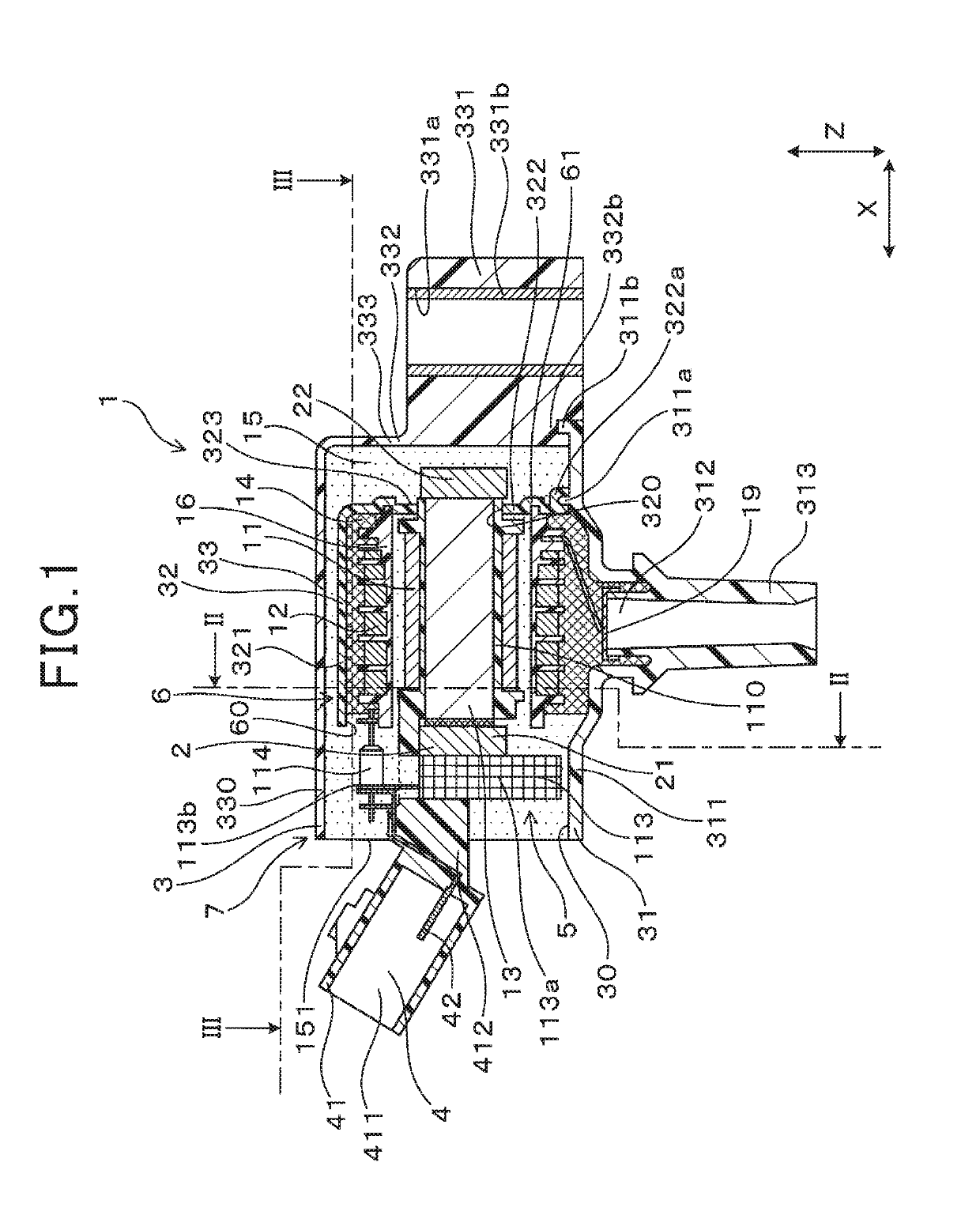
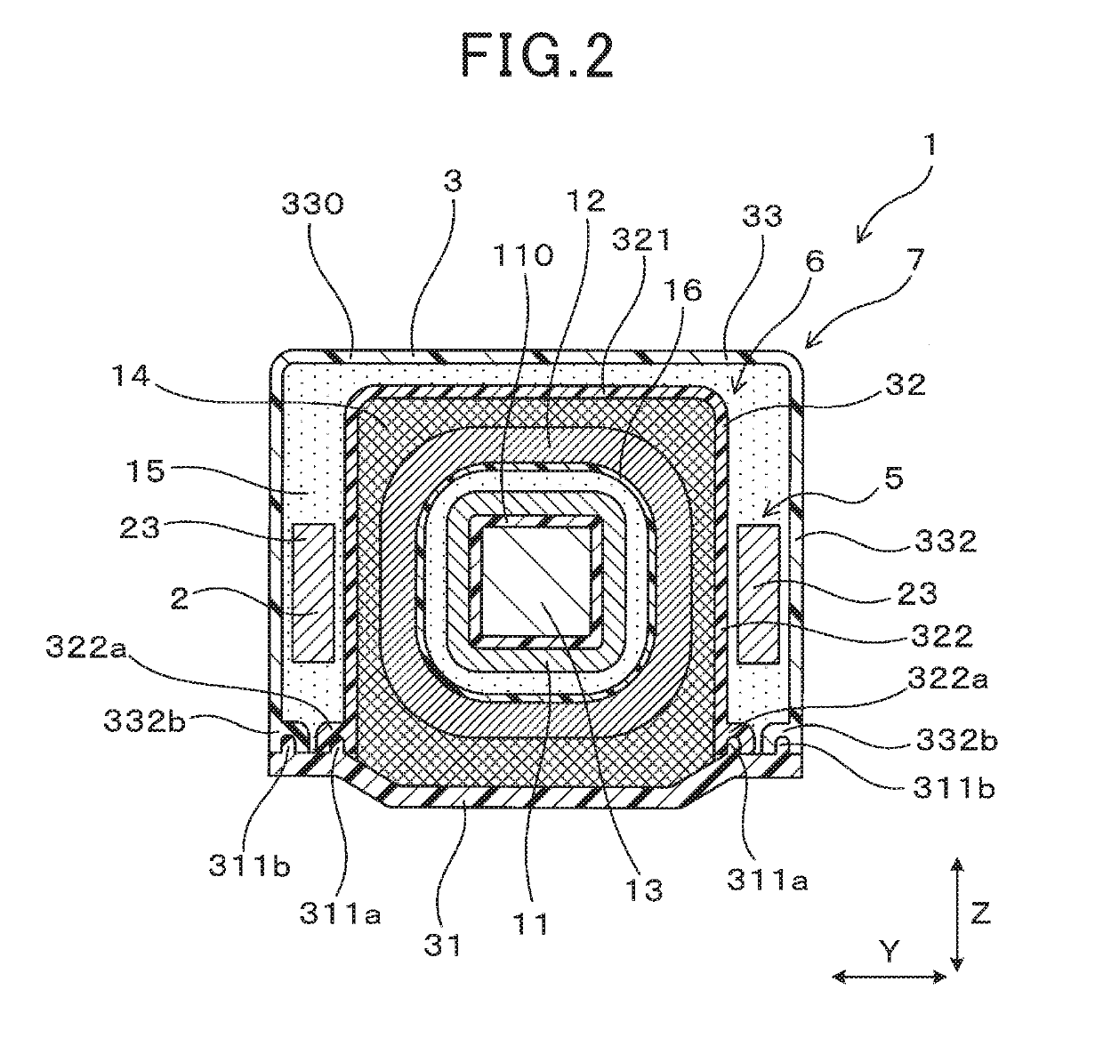
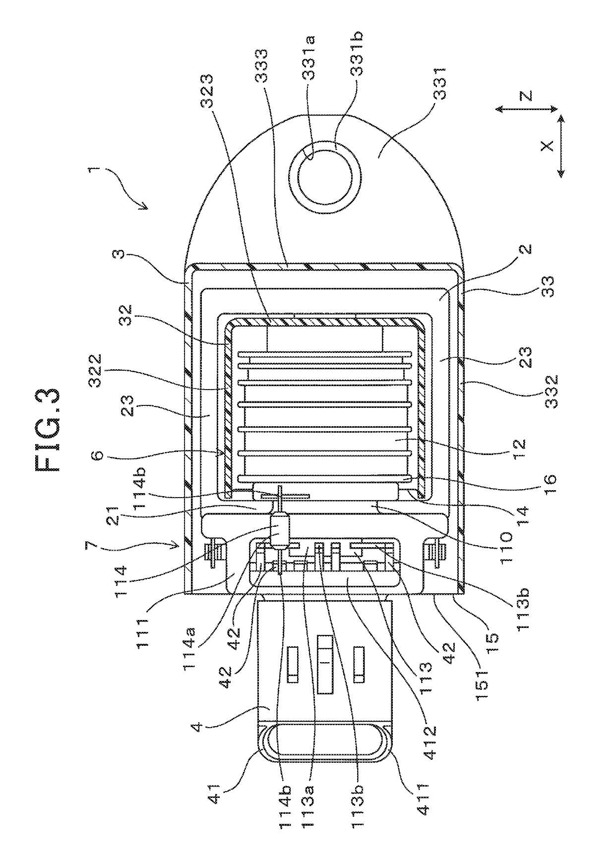
[0032]An ignition coil for an internal combustion engine will be described with reference to FIGS. 1 to 4.

[0033]As shown in FIG. 1, the ignition coil 1 for an internal combustion engine of a first embodiment includes a primary coil 11, a secondary coil 12, a center core 13, an outer core 2, a high voltage outputting section, a case 3, a first filler resin 14, a second filler resin 15 and a connector 4.

[0034]The secondary coil 12 is wound around a secondary spool 16 which is disposed on an outer peripheral side of the primary coil. The center core 13 is disposed on an inner peripheral side of the primary coil 11 and the secondary coil 12. The outer core 2 is disposed on an outer peripheral side of the first coil 11 and the second coil 12. The high voltage output section 19 has conductivity and externally outputs a voltage from the secondary coil 12. The case 3 accommodates the primary coil 11, the secondary coil 12, the secondary spool 16, the center core 13, the external core 2 and ...

second embodiment

[0093]In a second embodiment, filling regions inside the case 3 of the first filler resin 14 are different from the first embodiment, as shown in FIGS. 8 and 9. Specifically, in the second embodiment, the first filler resin 14 is filled into the inner side of the secondary spool 16 and the secondary coil 12 that is provided on the inside of the inner case 6, and also into the outer peripheral side of the primary spool 110 and the primary coil 11. As shown in FIG. 8, in the second embodiment, a configuration in which, a rear part of the primary spool 110 and a part that surrounds the through-hole 320 of the second case 32 that can be interlocked with each other, is provided. By interlocking the primary spool 110 and the second case 31, sealing between the primary spool 110 and the second case 32 is achieved, and leaking of the first filler resin 14 from the inner case 6 is thus avoided.

[0094]Other aspects of the second embodiment are the same as the first embodiment. It is noted that...

third embodiment

[0095]In a third embodiment, a disposed position of the igniter 113 is different from the first embodiment, as shown in FIG. 10. In the third embodiment, the igniter 113 is arranged on the inside of the inner case 6. The igniter 113 is also buried inside the first filler resin 14. The igniter 113 is provided on an upper side of the secondary coil 12. That is, the igniter 113 is positioned to have the main surface of the igniter body 113a opposed to the secondary coil 12, in the vertical direction Z.

[0096]Other aspects of the third embodiment are the same as the first embodiment. The same effects of the first embodiment may also be obtained in the third embodiment.


PUM


Abstract

A first filler resin is disposed to cover at least an outer peripheral side of a secondary spool and a secondary coil. The second filler resin is filled inside a case and seals a cover sealant which includes a primary coil, secondary spool, a secondary coil, a center core, an outer core and the first filler resin. The connector protrudes to an outside of the case. The case has a fixing portion. The second filler resin has a lower elasticity than the first filler resin. The ignition coil is manufactured by filling the first resin inside the case, and filling the second resin after the first resin is cured.

Description

CROSS REFERENCE[0001]The present application is based on Japanese application No. 2016-143275 submitted on Jul. 21, 2016, the entire contents of which is incorporated herein by reference.TECHNICAL FIELD[0002]The present disclosure relates to an ignition coil for an internal combustion engine and a manufacturing method thereof.RELATED ART[0003]Ignition coils for internal combustion engines include a primary coil and secondary coil magnetically coupled to each other, a metallic core, a case accommodating the above mentioned elements, and a connector which connects the ignition coil to external devices. In the case, a fixing portion is provided to extend to an outside of the case. The ignition coil is thus fixed to the internal combustion engine at the fixing portion. An inside of the case filled with a filler resin, and configuring elements, for example, the primary coil and the secondary coil, sealed inside the case.[0004]An ignition coil disclosed in patent literature 1 however uses...

Claims


Application Information

Patent Timeline
IPC IPC(8): H01F27/32F02P3/055H01F38/12H01F27/28H01F27/24H01F27/02H01F41/12
CPCH01F27/327F02P3/055H01F38/12H01F27/28H01F27/24H01F27/022H01F41/127F02P3/02F02P15/00
Inventor KONISHI, ATSUYUKI
Owner DENSO CORP
Why Eureka
Try Eureka