
Reverse drainage system capable of reducing water pressure at bottom of tunnel

A technology of drainage system and bottom water, applied in drainage, safety devices, mining equipment and other directions, can solve the problems of short time for renovating and constructing skylights, reduced overall elasticity, and high train density, avoiding the phenomenon of mud and mud, and meeting durability. requirements, the effect of reducing water pressure

Active Publication Date: 2016-08-24
CHINA RAILWAY ECONOMIC & PLANNING RES INST +2
View PDF10 Cites 3 Cited by
  • Summary
  • Abstract
  • Description
  • Claims
  • Application Information

AI Technical Summary

Problems solved by technology

Seriously affect the quality of the line, increase the workload of line maintenance, cause a great waste of labor and materials, and reduce the overall elasticity of the ballast bed due to the softening of the base and the compaction of the ballast, affecting the safe operation of the train
In addition, it is very difficult to control the disease at the bottom of the tunnel, especially for high-speed railway tunnels with ballastless tracks. Due to the high density of trains, the short time for repairing skylights, and the difficult maintenance of ballastless tracks, it is extremely difficult to eradicate them.

Method used


Image

  • Reverse drainage system capable of reducing water pressure at bottom of tunnel
  • Reverse drainage system capable of reducing water pressure at bottom of tunnel
  • Reverse drainage system capable of reducing water pressure at bottom of tunnel

Examples


Embodiment Construction

[0020] The present invention will be further described in detail below in conjunction with the accompanying drawings and specific embodiments.

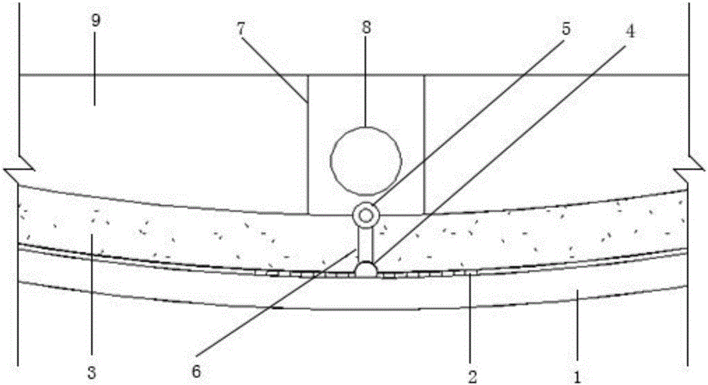
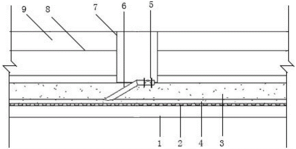
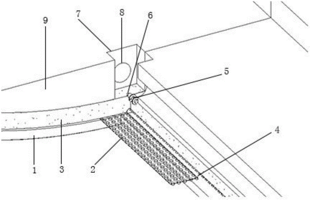
[0021] Such as Figure 1-3 As shown, a reverse drainage system to reduce the water pressure at the bottom of the tunnel, the implementation process of this step is as follows:

[0022] Step 1. Install a horizontal waterproof and drainage board 2 at the construction joint of the inverted arch between the bottom primary support 1 and the inverted arch lining 3. The horizontal waterproof and drainage board 2 is connected to the longitudinal water collection system at the bottom of the tunnel, and is located in the middle and upper part of the vertical water collection system. A round pipe 4 with a diameter of 150-200 mm is provided.

[0023] Step 2: Install the oblique drainage pipe 6 at the position of the inspection well and connect the circular pipe 4 along the 30° oblique direction of the drainage longitudinal slope of the tunnel, t...


PUM


Abstract

The invention discloses a reverse drainage system capable of reducing water pressure at the bottom of a tunnel. A transverse water collection system is arranged at the bottom position of a construction joint of an inverted arch, a longitudinal water guide system is arranged at the bottom of the inverted arch and is laid along the longitudinal direction, and an oblique water return system is arranged under an inspection well and is communicated with a longitudinal water collection pipe along the inclined direction; a transverse waterproof and drainage board is laid between a preliminary bracing and a lining of the inverted arch. The longitudinal water guide system consists of a longitudinal drain board and a circular tube, wherein the circular tube is arranged above a center line of the bottom of the preliminary bracing. The transverse water collection system is used for water prevention of a bottom structure of the tunnel and leading water into the longitudinal water guide system, and the water is discharged from the longitudinal water guide system; an oblique drainage system is used for reversely discharging the water at the bottom of the tunnel into a manholes and a central ditch of the inverted arch by reverse flow. After the reverse drainage system is adopted, the bottom structure of the tunnel is avoided being excavated again, so that the normal operation of the tunnel is not influenced; furthermore, the drainage system at the bottom of the tunnel can be maintained, so that the requirement of durability is met, and the water pressure at the back of the secondary lining of the tunnel is effectively reduced.

Description

technical field [0001] The invention relates to a reverse drainage system for reducing water pressure at the bottom of a tunnel, belonging to the technical field of underground engineering waterproofing and drainage. Background technique [0002] With the rapid development of my country's transportation, energy, water conservancy and other infrastructure construction, the construction scale of tunnel projects is getting larger and larger. Taking railway tunnels as an example, by the end of December 2015, more than 13,000 railway tunnels had been built and put into operation in my country, with a total length of more than 13,000 kilometers; more than 3,700 railway tunnels were under construction, with a total length of more than 13,000 kilometers. 8,700 kilometers, more than all other countries combined. In addition, the total length of highway tunnels opened to traffic also exceeded 10,000 kilometers. When a large number of tunnel projects in my country have been put into o...

Claims


Application Information

Patent Timeline
IPC IPC(8): E21F16/02
CPCE21F16/02
Inventor 赵勇倪光斌李鹏飞林传年马伟斌纪茜尧杨云轩唐国荣田四明王志伟
Owner CHINA RAILWAY ECONOMIC & PLANNING RES INST
Learn More