Piston ring

A piston ring and ring body technology, applied in the field of piston rings, can solve the problems of piston ring sealing and wear resistance defects, gas blow-by, etc., and achieve the effect of improving the operating life and reducing the probability of overall structure damage

Active Publication Date: 2016-08-24
广州珠江气体工业有限公司
View PDF10 Cites 0 Cited by
  • Summary
  • Abstract
  • Description
  • Claims
  • Application Information

AI Technical Summary

Problems solved by technology

However, the above solution also has the following problem: in the piston top ring, the combustion gas passes through a plurality of grooves that are U-shaped or U-sha

Method used


Image

  • Piston ring
  • Piston ring
  • Piston ring

Examples


Example Embodiment

[0050] Table 1-2 shows the composition and performance parameters of the upper and lower ring bodies of the piston rings in Examples 1-4.

[0051] Table 1:

[0052]

[0053] Table 2:

[0054]

[0055] Through the above tests, the performance index of the obtained piston ring is better than that of the prior art, and its service life is greatly improved.

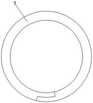
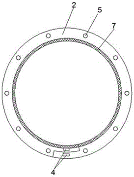
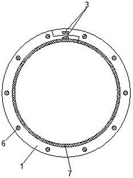
[0056] Attached below Figure 1-3 The structural improvement of the piston ring is described in detail.

[0057] The piston ring comprises an upper ring body 1 and a lower ring body 2, the upper ring body 1 and the lower ring body 2 are all provided with cross openings, the bottom surfaces of both ends of the upper ring body 1 are provided with bosses 3, and the lower ring body 1 The top surface of both ends of the body 2 is provided with grooves 4, and the boss 3 is connected with the groove 4. At the same time, the lower surface of the upper ring body 1 is evenly provided with a number of protruding rods 6, and the...


PUM


Abstract

A piston ring can be widely used on various power machines and comprises an upper ring body and a lower ring body which are each provided with a crossed opening; and the upper ring body and the lower ring body are both made from an iron-base alloy, and contained titanium, copper and rare earth elements perform modification treatment on the ion-base alloy. Meanwhile, the invention further provides a structure improvement of the piston ring, and by means of arrangement of a boss, a groove, a convex rod, a small hole, a large groove and a multi-layer structure, the obtained piston ring has good mechanical performance and long service life.

Description

technical field [0001] This application relates to a piston ring, in particular to a piston ring used in various power machines, such as steam engines, diesel engines, gasoline engines, compressors, hydraulic machines, etc. The piston rings can be widely used in automobiles, trains, ships , boats, yachts, various large agricultural machinery and other fields. Background technique [0002] Piston rings are metal rings used to embed in piston grooves. Piston rings are divided into two types: compression rings and oil rings. The compression ring is used to seal the combustible mixture in the combustion chamber; the oil ring is used to scrape excess oil from the cylinder. The piston ring is a metal elastic ring with a large outward expansion deformation, which is assembled into the corresponding annular groove of the section. The reciprocating and rotating piston rings rely on the pressure difference of gas or liquid to form a seal between the outer circular surface of the rin...

Claims


Application Information

Patent Timeline
IPC IPC(8): F16J9/26F16J9/16F02F5/00C22C37/10
CPCC22C37/10F02F5/00F16J9/16F16J9/26
Inventor 唐思钊
Owner 广州珠江气体工业有限公司
Why Eureka
Try Eureka