Delay performance test method and test device for fractional delay filter

A fractional delay and test method technology, applied in measurement devices, electronic circuit testing, instruments, etc., can solve the problems of high cost of analog delay lines, restricting the application of array radar, and receiving beam pointing offset.

Active Publication Date: 2016-08-24
CHINA ELECTRONIC TECH GRP CORP NO 38 RES INST
View PDF6 Cites 5 Cited by
  • Summary
  • Abstract
  • Description
  • Claims
  • Application Information

AI Technical Summary

Problems solved by technology

[0003] In an array radar system, due to differences in cables, analog and digital devices, and other components, the delay of broadband signals passing through multiple analog channels is different. The traditional phase control method will cause the pointing deviation of the receiving b

Method used


Image

  • Delay performance test method and test device for fractional delay filter
  • Delay performance test method and test device for fractional delay filter
  • Delay performance test method and test device for fractional delay filter

Examples


Embodiment 1

[0044] The method for testing the delay performance of the fractional delay filter of the present invention can be implemented in the FPGA, and directly reflects the fractional delay performance of the hardware. Fractional delay filter delay performance test method can be implemented in the form of software App, designed as a fractional delay filter delay performance test device, so that it can be conveniently implemented in electronic equipment with intelligent control. In addition, it can also It can be programmed into the control chip.

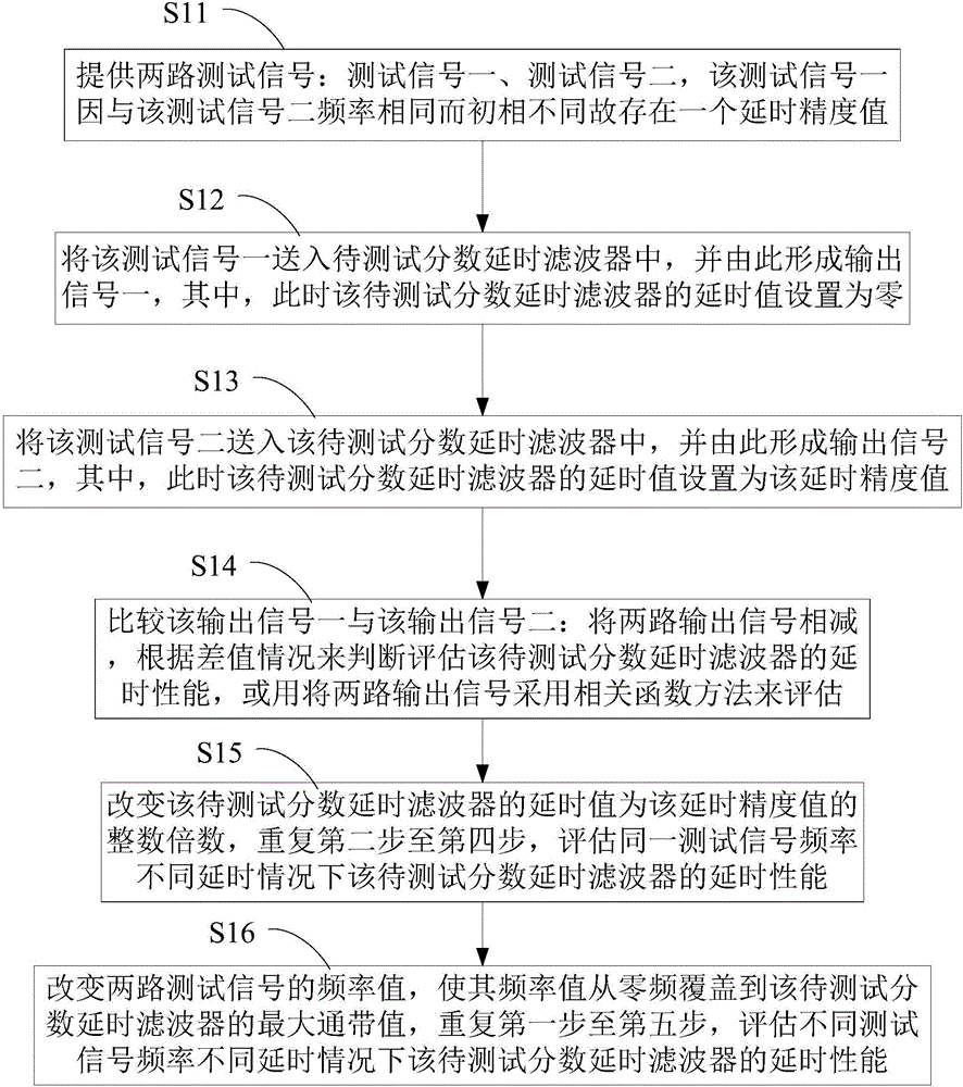
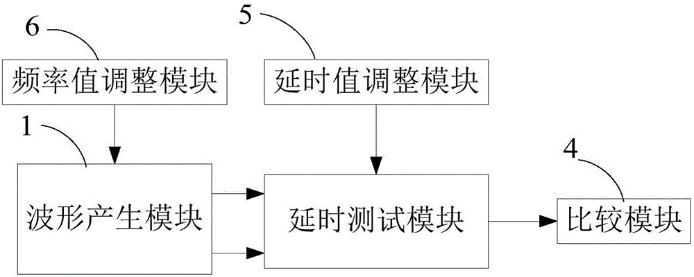
[0045] Please also refer to figure 1 and figure 2 , the fractional delay filter delay performance testing method of the present embodiment comprises the following steps, and the fractional delay filter delay performance test device corresponding thereto simultaneously comprises a waveform generation module 1, a delay test module, a comparison module 4, a delay A time value adjustment module 5 and a frequency value adjustment module 6 . ...

Embodiment 2

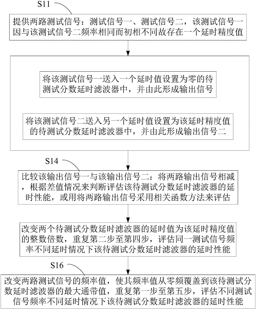
[0059] Please also refer to image 3 and Figure 4 , the fractional delay filter delay performance test method of the present embodiment and the fractional delay filter delay performance test device applying the method are basically the same as the method and device of embodiment 1, and the difference is that: embodiment 1 Steps S12 and S13 run synchronously, so Embodiment 2 can test two fractional delay filters to be tested.

[0060] Therefore, in the second step S12, the test signal one is sent into a fractional delay filter to be tested with a delay value set to zero, and thus an output signal one is formed; and in the third step S13, the The test signal 2 is sent to another fractional delay filter to be tested whose delay value is set to the delay accuracy value, and the output signal 2 is thus formed; then the corresponding two fractional delay filters to be tested are evaluated in subsequent steps The delay performance of the device.

[0061] That is, the delay test m...


PUM


Abstract

The invention discloses a delay performance test method and a test device for a fractional delay filter. The delay performance test method comprises the following steps: providing two test signals between which a delay precision value exists; respectively transmitting the two test signals into two fractional delay filters to be tested with delay values respectively set to be zero and equal to the delay precision value, to form two output signals; comparing the two output signals; subtracting the two output signals, and judging and estimating the delay performance of the fractional delay filters to be tested according to a difference, or estimating the delay performance by implementing a relevant function method on the two output signals; changing the delay value into an integral multiple of the delay precision value or change frequency values of the two test signals, and repeating the above steps. The invention further discloses a delay performance test device for the fractional delay filter by adopting the method, another delay performance test method for the fractional delay filter and a delay performance test device for the fractional delay filter by adopting the another delay performance test method.

Description

technical field [0001] The invention belongs to a delay performance testing method in the field of digital signal processing and a delay performance testing device using the delay performance testing method, in particular to a fractional delay filter delay performance testing method and the application of the fractional delay The invention discloses a fractional delay filter delay performance test device of a filter delay performance test method. Background technique [0002] Phased array radar has agile beam scanning and agility capabilities, and can achieve the advantages of multi-target acquisition and tracking. Broadband signals can effectively improve the anti-jamming ability of phased array radar, and can achieve higher ranging accuracy and resolution, which is conducive to imaging, identification and classification of targets. Therefore, broadband phased array radar technology is one of the main directions of modern radar technology development. [0003] In an array...

Claims


Application Information

Patent Timeline
IPC IPC(8): G01R31/28
CPCG01R31/282
Inventor 朱亮张卫清朱文松胡晓芳
Owner CHINA ELECTRONIC TECH GRP CORP NO 38 RES INST
Why Eureka
Try Eureka