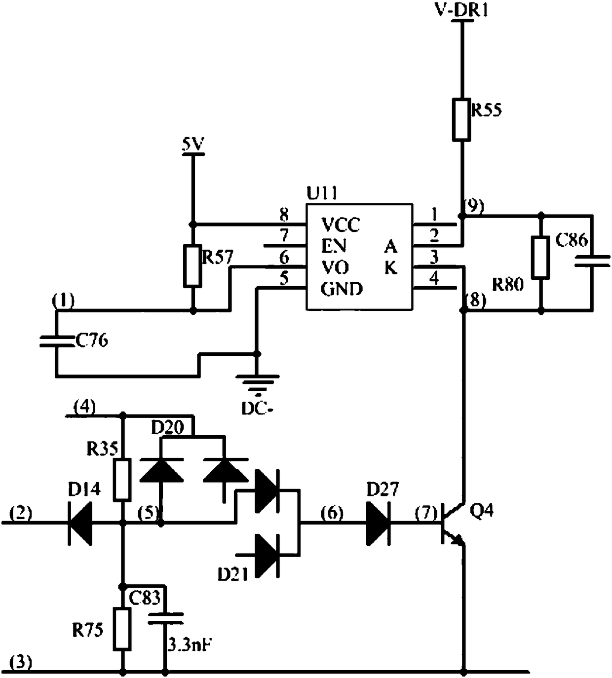
A short-circuit monitoring circuit for mos tubes in a drive circuit
A technology of MOS tube and driving circuit, applied in the field of short circuit monitoring circuit, can solve the problems of MOS tube pass-through, MOS tube protection effect is not large, increase R&D cost, etc., and achieve the effect of small area, simple and reliable circuit construction, and fewer components.
- Summary
- Abstract
- Description
- Claims
- Application Information
AI Technical Summary
Problems solved by technology
Method used
Image
Examples
Embodiment Construction
[0011] Such as figure 1 As shown, this short-circuit monitoring circuit for MOS transistors in the drive circuit includes: a drive signal input terminal (4), an absorption filter circuit, first, second, and third diodes (D14, D21, D27), Transistor (Q4), optocoupler (U11), fault signal detection terminal (1), micro control unit MCU;
[0012] The absorbing filter circuit includes a first resistor (R35), a fourth diode (D20), and a first capacitor (C83), and the anode of the first capacitor (C83) is connected to the anode and cathode of the first diode (D14). Connect the S end of the MOS tube, the anode of the fourth diode (D20) is connected to the anode of the first diode (D14) and the cathode is connected to the drive signal input terminal (4);
[0013] The first, second, third, and fourth diodes (D14, D21, D27, D20) are all ultra-fast recovery diodes, and the optocoupler is a fast optocoupler;
[0014] When the MOS tube works normally, the current flows through the drive sig...
PUM
 Abstract
Description
Claims
Application Information
 - R&D
- Intellectual Property
- Life Sciences
- Materials
- Tech Scout
- Unparalleled Data Quality
- Higher Quality Content
- 60% Fewer Hallucinations
Browse by: Latest US Patents, China's latest patents, Technical Efficacy Thesaurus, Application Domain, Technology Topic, Popular Technical Reports.
© 2025 PatSnap. All rights reserved.Legal|Privacy policy|Modern Slavery Act Transparency Statement|Sitemap|About US| Contact US: help@patsnap.com

