Driving device of cooling fan of engine

A technology for engine cooling and driving devices, which is applied in the direction of engine cooling, cooling device control devices, engine components, etc., and can solve problems such as waste of hydraulic oil flow

Inactive Publication Date: 2016-08-31
江苏卡威汽车研究院有限公司
View PDF7 Cites 5 Cited by
  • Summary
  • Abstract
  • Description
  • Claims
  • Application Information

AI Technical Summary

Problems solved by technology

Therefore, with the acceleration and deceleration of the engine, the operation of increasing the rotation speed of the hydraulic motor for the cooling fan to the target rotation speed is repeated. When w

Method used


Image

  • Driving device of cooling fan of engine
  • Driving device of cooling fan of engine
  • Driving device of cooling fan of engine

Examples


Embodiment Construction

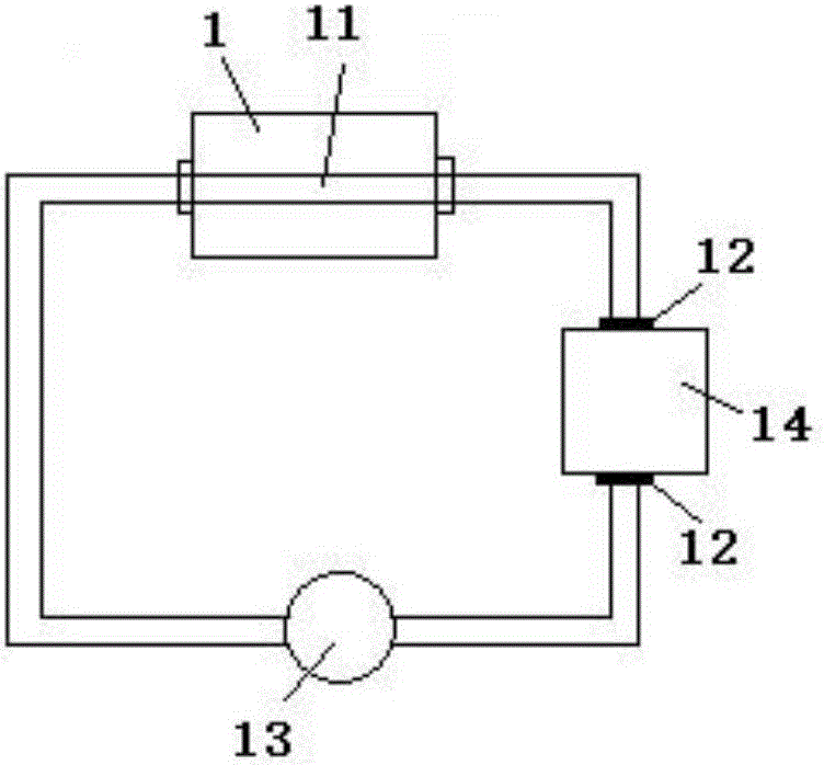
[0014] like Figure 1-Figure 3 The driving device of the engine cooling fan shown includes an engine 1, an engine water cooling system, an engine air cooling system and a control unit.

[0015] The engine water cooling system includes a water tank 14, a water pump 13 and a water pipe 11 embedded in the engine 1 housing. The water tank 14 is provided with a water inlet and a water outlet. The inlet and the outlet of the water pipe 11 communicate with the water inlet of the water tank 14.

[0016] Both the water outlet and the water inlet of the water tank 14 are provided with water temperature sensors 12, and there are two water temperature sensors 12 in total.

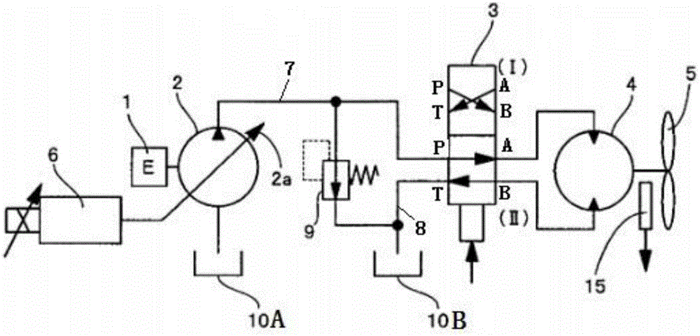
[0017] The engine air-cooling system includes a swash plate variable pump 2 driven by the engine 1, the output shaft of the engine 1 is connected to the rotating shaft of the swash plate variable pump 2, and the swash plate variable pump 2 passes through the flow control valve 6, two-position The four-way solenoid va...


PUM


Abstract

The invention discloses a driving device of a cooling fan of an engine and belongs to the hydraulic drive field. The driving device of the cooling fan of the engine comprises the engine, an engine water cooling system, an engine air cooling system and a control unit; the engine water cooling system comprises a water tank; the positions of a water outlet and a water inlet of the water tank are each provided with a water temperature sensor; the engine air cooling system comprises a swash plate variable pump driven by the engine; the swash plate variable pump is connected with a hydraulic motor through a flow control valve and a two-position four-way electromagnetic valve in sequence; the hydraulic motor drives the fan; an inlet of the swash plate variable pump is connected with an oil inlet tank; and the position of an outlet of the swash plate variable pump is provided with an oil temperature sensor. The invention provides the driving device of the cooling fan of the engine. When the rotating speed of the cooling fan is increased to a target rotating speed, the flow of hydraulic oil sprayed out of a hydraulic pump can be reduced to the largest extent, and energy losses can be reduced.

Description

technical field [0001] The invention belongs to the field of hydraulic drive, in particular to a drive device for an engine cooling fan. Background technique [0002] In hydraulically driven machines such as construction, machinery, and vehicles, the hydraulic oil discharged from the hydraulic pump for the cooling fan driven by the engine is supplied to the hydraulic motor that rotates the cooling fan. A work vehicle that frequently accelerates and decelerates the engine, for example, in a work vehicle such as a wheel loader, when performing operations such as loading and unloading, the engine is frequently accelerated due to repeated forward, reverse and V-shaped operations. slow down operation. If the engine is frequently accelerated and decelerated, the rotation speed of the hydraulic pump for the cooling fan indirectly driven by the rotation of the engine also accelerates and decelerates according to the rotation speed of the engine, the engine drives the hydraulic pump...

Claims


Application Information

Patent Timeline
IPC IPC(8): F01P5/04F01P7/04F01P11/16
CPCF01P5/04F01P7/044F01P11/16F01P2025/40F01P2037/00
Inventor 刘佳孟明华胡成
Owner 江苏卡威汽车研究院有限公司
Why Eureka
Try Eureka