

Large nuclear reactor molten pool natural-convection heat transfer test system and method
A technology of natural convection and nuclear reactor, applied in the field of natural convection heat transfer test system of large nuclear reactor melting pool, it can solve the problem of small Rayleigh number of melting pool and achieve the effect of ensuring water temperature, reducing impact and facilitating flow adjustment
- Summary
- Abstract
- Description
- Claims
- Application Information
AI Technical Summary
Problems solved by technology
Method used
Image

Examples
Embodiment Construction
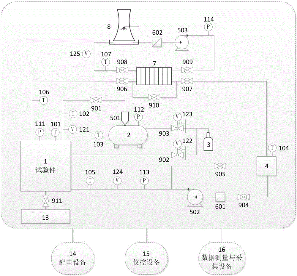
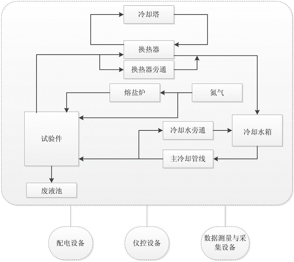
[0027] Below in conjunction with accompanying drawing and specific embodiment the present invention is described in detail:
[0028] Such as figure 1 and figure 2 As shown, the present invention is a large-scale nuclear reactor fusion pool natural convection heat transfer test system and method. The test system includes a large-scale nuclear reactor fusion pool natural convection heat transfer test piece 1, a molten salt heating furnace 2 that provides high-temperature molten matter, and The nitrogen source 3 connected to the test piece and the molten salt furnace, and the cooling water system; the first centrifugal pump 502 drives the water in the cooling water tank 4 to take away the decay heat source through the cooling channel of the test piece 1, and the heated cooling water passes through the plate heat exchange Return to the cooling water tank 4 after the cooling of the device 7 and the cooling tower 8 returns to the initial water temperature; the test ends when the t...
PUM
 Abstract
Description
Claims
Application Information