Multilayer ceramic capacitor of low ESL

A multi-layer ceramic and capacitor technology, applied in the direction of multilayer capacitors, fixed capacitor dielectrics, fixed capacitor terminals, etc., can solve the problems that capacitors cannot be applied to high-frequency circuits, the self-resonant frequency of capacitors decreases, and the equivalent inductance of capacitors increases. , to increase the adhesion amount and adhesion strength, increase the self-resonant frequency, and reduce the effect of ESL

Inactive Publication Date: 2016-08-31
FUJIAN TORCH ELECTRON TECH CO LTD
View PDF5 Cites 6 Cited by
  • Summary
  • Abstract
  • Description
  • Claims
  • Application Information

AI Technical Summary

Problems solved by technology

On the other hand, there are multiple 90° bends in the lead wire 2. Under the condition of high frequency and high current, the bent terminal will increase the eddy current and directly increase the equivalent inductance (ESL) of the capacitor.
The increase of ESL directly leads to the decrease of the self-resonant frequency of the capacitor, so that the capacitor cannot be used in high-frequency circuits

Method used


Image

  • Multilayer ceramic capacitor of low ESL
  • Multilayer ceramic capacitor of low ESL
  • Multilayer ceramic capacitor of low ESL

Examples


Embodiment 1

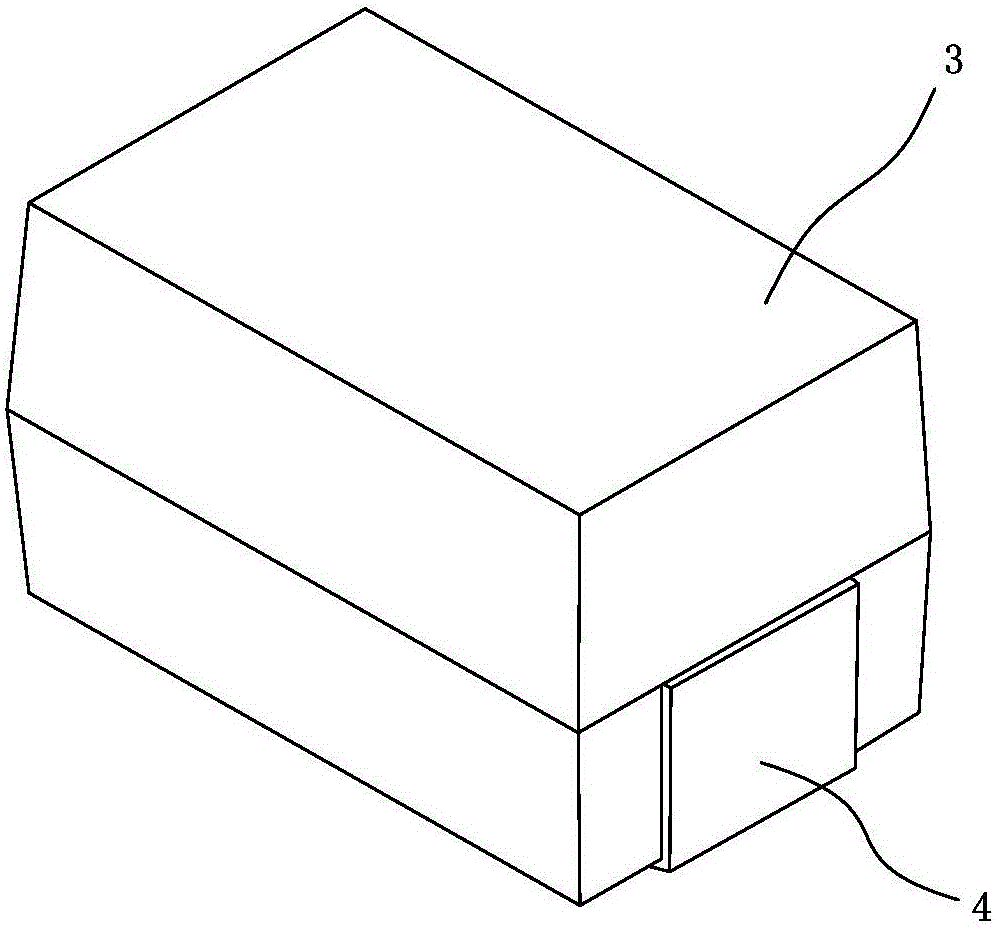
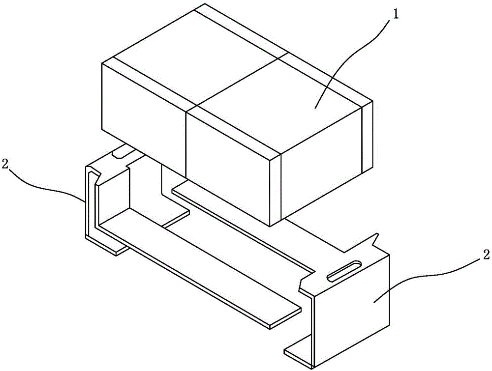
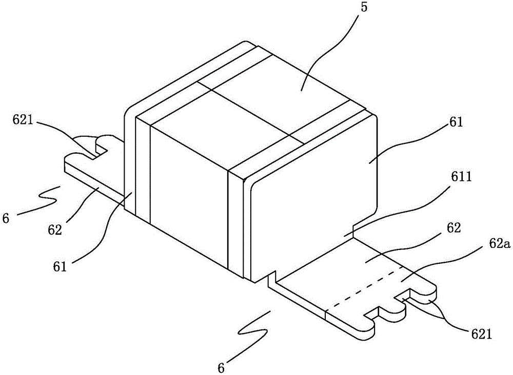
[0025] Example one, reference image 3 with Figure 4 As shown, a low ESL multilayer ceramic capacitor includes a ceramic core 5, two leads 6 and an insulating shell 7.

[0026] The ceramic core 5 is a rectangular parallelepiped, which is mainly composed of a dielectric, an inner electrode sheet and an outer electrode sheet. The two outer electrode sheets are arranged on two opposite faces of the ceramic core body 5. This is a well-known prior art and will not be described in detail here.

[0027] The lead 6 is an integrally formed "L"-shaped structure, which is composed of a conductive plate 61 and a welding plate 62 that are connected perpendicularly to each other. The conductive plate 61 and the welding plate 62 are approximately rectangular, and the conductive plate 61 has a protrusion connected to the welding plate 62 611.

[0028] The conductive plates 61 of the two leads 6 are respectively attached to the two opposite surfaces of the ceramic core 5 and electrically connected t...

Embodiment 2

[0029] The second embodiment, the basic structure is the same as the first embodiment, the main difference lies in the structure of the lead 8, which includes a vertically extending conductive plate 81, a horizontal welding plate 82 connected to the conductive plate 81 and extending horizontally, and a connecting horizontal welding plate 82 and a vertical welding plate 83 extending vertically. The conductive plate 81 is electrically connected to the ceramic core 5 and is covered by the insulating housing 7. The horizontal welding plate 82 is located at the bottom of the insulating housing 7, and the vertical welding plate 83 is located at the bottom of the insulating housing 7. At least the bottom surface of the horizontal welding plate 82 and the outer side surface of the vertical welding plate 83 are exposed outside the insulating housing 7. The vertical welding plate 83 is formed with three solder filling holes 831 close to the horizontal welding plate 82. The holes 831 are a...


PUM


Abstract

A multilayer ceramic capacitor of a low ESL comprises a ceramic core body, two lead wires conductively connected to the ceramic core body and an insulating shell wrapping the ceramic core body. The lead wires are an ''L''-shaped structure formed by a current-conducting plate and a welding plate which are vertically connected to each other. The current-conducting plate and the ceramic core body are conductively connected and are covered by the insulating shell. The welding plate is located at a bottom of the insulating shell and possesses a welding segment which is laterally stretched out of the insulating shell. Through using the ''L''-shaped lead wires, lead wire lengths are greatly reduced and bending angles of the lead wires are decreased so that the ESL can be greatly reduced, a self-resonant frequency of the capacitor is increased and the capacitor can be applied in a high frequency circuit.

Description

Technical field [0001] The invention relates to a multilayer ceramic capacitor. Background technique [0002] Such as figure 1 with figure 2 As shown, the multilayer ceramic capacitor mainly includes a ceramic core 1, two leads 2 and an insulating shell 3. The ceramic core 1 includes a plurality of first and second inner electrode plates spaced in parallel and alternately arranged, arranged in the first and second The dielectric between the two inner electrode sheets, the first outer electrode sheet conductively connected to each first inner electrode sheet, and the second outer electrode sheet conductively connected to each second inner electrode sheet. Generally, the ceramic core 1 is a rectangular parallelepiped. 1. The second external electrode sheets are arranged on two opposite sides of the ceramic core 1, the two leads 2 are electrically connected to the first and second external electrode sheets, respectively, and the insulating shell 3 wraps the ceramic core, and the in...

Claims


Application Information

Patent Timeline
Patent Type & Authority Applications(China)
IPC IPC(8): H01G4/232H01G4/30
CPCH01G4/12H01G4/232H01G4/30
Inventor 贺卫东吴文辉张子山蔡劲军
Owner FUJIAN TORCH ELECTRON TECH CO LTD
Why Eureka
Try Eureka